This is a simple audio-frequency (AF) amplifier using the popular audio amplifier IC TDA2003. The IC comes in a 5-pin TO-220B package.
Circuit and working
Fig. 1 shows the circuit diagram of the 3W/6W AF amplifier built around IC TDA2003 (IC1), an 8-ohm, 6-watt speaker (LS1) and a few other components.
Circuit diagram of 3W to 6W audio amplifier using TDA2003
The amplifier IC delivers 3W output power using a 6V, 500mA power supply, and 6W output power using a 12V, 500mA power supply, with an 8-ohm, 6-watt speaker.
Pin 1 of TDA2003 is the input terminal, which is connected to ground through a 100-kilo-ohm resistor. The audio frequency (or audio signal) is fed to pin 1 of IC1 through the combination of a 10-kilo-ohm potmeter (VR1) and capacitors C1 and C2. Potmeter VR1 is used as volume control. Pin 3 of IC1 is connected to ground. Pin 4 is the output terminal, which is connected to one terminal of the speaker through a 470µF, 16V capacitor (C5). It is also connected to ground through a 0.1µF capacitor (C4) and a 1-ohm resistor (R4).
Pin 5 of IC1 is connected to +6V power supply via switch S1. Power supply can be provided through a 6V battery or a 6V DC adaptor. Use of a suitable heatsink is recommended for IC1.
Construction and testing
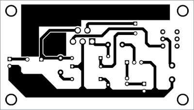
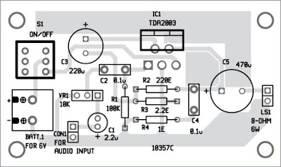
An actual-size, single-side PCB for 3W/6W audio amplifier using TDA2003 is shown in Fig. 2 and its components layout in Fig. 3. After assembling the circuit on the PCB, enclose it in a suitable box.
PCB layout of 3W to 6W audio amplifier using TDA2003
Components layout for the PCB
Solder TDA2003 and other components using a 25W soldering iron. Use a 2-pin connector for input and output connectors, to make your prototype safe and clean.
For testing the circuit, connect a 6V battery to the circuit. Also, connect an 8-ohm, 6-watt speaker to LS1.
If a 12V DC supply is used, voltage ratings of C1, C3 and C5 should be 25V or above.
Take a metal screwdriver and gently touch at input pin 1 of IC1. If your circuit is wired properly, you will hear a humming sound from the speaker. Else, vary potmeter VR1 to increase the volume until humming sound is heard from the speaker. Now your circuit is ready to use.
Circuit and working
Fig. 1 shows the circuit diagram of the 3W/6W AF amplifier built around IC TDA2003 (IC1), an 8-ohm, 6-watt speaker (LS1) and a few other components.
Circuit diagram of 3W to 6W audio amplifier using TDA2003
Pin 1 of TDA2003 is the input terminal, which is connected to ground through a 100-kilo-ohm resistor. The audio frequency (or audio signal) is fed to pin 1 of IC1 through the combination of a 10-kilo-ohm potmeter (VR1) and capacitors C1 and C2. Potmeter VR1 is used as volume control. Pin 3 of IC1 is connected to ground. Pin 4 is the output terminal, which is connected to one terminal of the speaker through a 470µF, 16V capacitor (C5). It is also connected to ground through a 0.1µF capacitor (C4) and a 1-ohm resistor (R4).
Pin 5 of IC1 is connected to +6V power supply via switch S1. Power supply can be provided through a 6V battery or a 6V DC adaptor. Use of a suitable heatsink is recommended for IC1.
Construction and testing
An actual-size, single-side PCB for 3W/6W audio amplifier using TDA2003 is shown in Fig. 2 and its components layout in Fig. 3. After assembling the circuit on the PCB, enclose it in a suitable box.
PCB layout of 3W to 6W audio amplifier using TDA2003
Components layout for the PCB
Solder TDA2003 and other components using a 25W soldering iron. Use a 2-pin connector for input and output connectors, to make your prototype safe and clean.
For testing the circuit, connect a 6V battery to the circuit. Also, connect an 8-ohm, 6-watt speaker to LS1.
If a 12V DC supply is used, voltage ratings of C1, C3 and C5 should be 25V or above.
Take a metal screwdriver and gently touch at input pin 1 of IC1. If your circuit is wired properly, you will hear a humming sound from the speaker. Else, vary potmeter VR1 to increase the volume until humming sound is heard from the speaker. Now your circuit is ready to use.
Author By: Raj K. Gorkhali : EFY


0 comments:
Post a Comment