Showing posts with label Automotive. Show all posts

Car Voltage Gauge

The Car Voltage Gauge is based on 3 parts. The input circuit is an Analog to Digital Converter (IC2 CA3162E). The purpose of this chip is to sample an analog voltage and convert it to a decimal value which is read by a Display/Decoder Driver (IC1 CA3161E). This chip will turn each seven segment display on through the driver transistor Q1 - Q3. The power is derived from the car and is converted to 5 volts by the 5 volt regulator. The circuit works as follows: The 10uf capacitor is charged up by the cars voltage. Its value is then read by IC2 and a decimal value of that voltage is provided to IC1 which multiplexes the three display units.

Car Voltage Gauge Circuit Diagram:
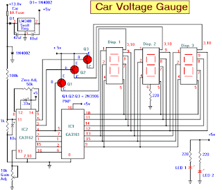

Voltage Circuit Diagram
 
Each display is turned on sequentially with its appropriate value displayed. The transistors Q1 through Q3 control the drive to each seven segment display. By monitoring the cars voltage with an accurate multimeter you can adjust the "Zero Adj." pot and the "Gain Adj." pot for accurate readings. LED 1 and 2 are optional. They can be used to indicate power on or can light up a cut out display that says "Volts". This can be made by a plastic module that has a thin plastic cover on it with the word "Volts" cut into it. The LED's would be mounted inside the module.
read more...

Motor Bike and Car Turning Signal Indicator with 555 Timer IC

Here is electronic circuit project for Motor Bike and Car Turning Signal Indicator. In our daily life we see vehicles turning indicators when they turn left or right. It looks like Simple LED Blinking. But it's not only simple blinking LEDs inside indicators of vehicles. Here we are building a fancy Car/Bike Turning Indicator Circuit using 555 Timer IC, with four LEDs glowing one by one in a particular pattern and we can control the speed or frequency of this LED indicator by simply turning a Potentiometer.

Motor Bike and Car Turning Signal Indicator Circuit Diagram:

Indicator

Parts List:

  • BC547 or MPS A42 NPN transistor -4
  • Bread Board -1
  • 555 Timer IC -1
  • 1K -1
  • 10k POT -1
  • 10K -6
  • 68K -1
  • Power Supply
  • LED -4
  • 10uF Capacitor -1
  • 470uF -1
  • 1N4148 Diode -2
  • 9V Battery -1
  • Jumper wire
In this Bike Turning Signal Indicator circuit, we have used one 10K and 1K resistors and a capacitor for generating a delay. The 1n4148 diode is connected in reverse bias at the output pin of 555 timer IC to maintain a constant current. Due to base current BC547/MPS42A (NPN) Transistor drive, the LED’s ON and OFF. LEDs are connected to the transistor through a 220ohm resistor with respect to Vcc. This 220ohm resistor will save LED to may get damaged.


read more...

Simple 3 Volts Car Adapter

This 3 volts Car Adapter circuit is based on a standard LT1074CT switching regulator IC. The schematic shows the LT1074CT used as a positive step-down or ‘buck’ converter. The ‘switcher’ is used to convert a +12-volt car battery voltage down to +3 volts for use with the personal hi-fi’s and handheld games for the author’s two boisterous children on long car journeys. Note at under ten years of age, children will rarely be hi-fi aficionado’s and are generally not concerned with any noise generated by the ‘switcher ‘circuit.

3 volts car adapter circuit diagram:


 3 volts car adapter circuit diagram

The circuit is connected to the car +12-V system via the cigarette lighter socket — is advisable to use a fused version of the cigarette lighter plug. The +12-V arrives on the board via screw- terminal block J2. Diode D2 provides a reverse voltage protection, while C3 decouples the input to the switcher IC.

The LT1074CT briskly switches the supply voltage on and off in response to the signal applied to its F/B input, to the extent that the average output voltage is at the required level. The values of potential divider resistors R1-R3 have been chosen to attenuate the output voltage so that there is 2.5 V at the F/B pin. The difference between the attenuated output voltage and the internal 2.5-V reference is used to control the modulation effect of the switcher.

Components R2 and C2 provide frequency stabilisation for the feedback loop. Inductor L1 along with the LT1074CT form the main switching components, while C1 provides decoupling for the output load. The 3-V output voltage is taken from screw terminal J1. With this circuit built, boxed up and installed in your car, you can look forward to possibly your first ‘quiet’ long car journey.


Author By: P. MARIAN
read more...

Low-Cost Low State Car Battery Indicator

Here is very simple low-cost electronic circuit project of low state car battery indicator circuit. This electronic circuit diagram designed using few common electronic parts. This low state battery electronic project can be used to monitor car battery voltage.

Low-Cost Low State Car Battery Indicator Circuit Diagram:

Indicator Circuit Diagram

The warning light LED indicates when battery indicates battery voltage falls bellow level set by 10k potentiometer, if the battery is defective or needs charging if cranking drops battery voltage bellow preset safe limit.

This circuit project is very simple so it not requires some other explanation.


read more...

Fog Lamp Sensor

For several years now, a rear fog lamp has been mandatory for trailers and caravans in order to improve visibility under foggy conditions. When this fog lamp is switched on, the fog lamp of the pulling vehicle must be switched of to avoid irritating reflections. For this purpose, a mechanical switch is now built into the 13-way female connector in order to switch of the fog lamp of the pulling vehicle and switch on the fog lamp of the trailer or caravan. For anyone who uses a 7-way connector, this switching can also be implemented electronically with the aid of the circuit illustrated here.

Fog Lamp Sensor Circuit Diagram:

Fog Lamp Sensor Circuit Diagram
 
Here a type P521 optocoupler detects whether the fog lamp of the caravan or trailer is connected. If the fog lamp is switched on in the car, a current flows through the caravan fog lamp via diodes D1 and D2. This causes the LED in the optocoupler to light up, with the result that the photo-transistor conducts and energies the relay via transistor T1. The relay switches of the fog lamp of the car. For anyone who’s not all thumbs, this small circuit can easily be built on a small piece of perforated circuit board and then fitted somewhere close to the rear lamp fitting of the pulling vehicle. Link


read more...

Automatically Lights On! Schematic

This circuit ensures that you will never again forget to switch on the lights of your car. As soon as the engine is running, the dipped beams and the sidelights are automatically switched on. The circuit also causes the dipped beams to be extinguished as soon as the main beams are switched on. As you can see from the schematic diagram, no special components are needed.

When the engine is running, the alternator will generate a voltage of more than 14 V. Diode D1 reduces this voltage by 5.6 V and passes it to the base of T1 via R1. Due to the resulting current, T1 conducts. The amplified current flows via R3, the base of T3 and D3 to ground. This causes T3 to also conduct and energize relay Re1.

Lights On  Circuit Diagram :

Automatically Lights On! Schematic
 
If the driver now switches on the main beams, a current flows through D2 and R2 into the base of T2, causing this transistor to conduct. As a result, the voltage on the base of T3 drops, causing T3 to cut off and the relay to drop out.

When the main beams are switched off, the previous situation is restored, and the relay again engages. The dipped beams and the sidelights are switched by the contacts of relay Re1. Diodes D5 and D6 ensure that the sidelights are illuminated if either the dimmed beams or the main beams are switched on. In practice, this means that the sidelights will be on whenever the engine is running, regardless of whether the main beams are switched on.


read more...

Car Backup Alarm

Here is Simple and low-cost electronic circuit project for car backup alarm, this project make is very easy.  The brake lights of the automobile trigger this circuit on and off.

Car Backup Alarm Circuit Diagram:


This save the annoyance of the alarm when it is not needed. This is an older circuit which was published in Popular Electronics Magazine, but still a good circuit today.


read more...

Ultrasonic Parking System using Transistors

Here is a very simple Electronic Circuit Project for ultrasonic parking system using transistors. ultrasonic parking system can be designed using this electronic circuit project . This ultrasonic parking system uses few common electronic parts like :transistors, resistors, capacitors and diodes .

Ultrasonic Parking System using Transistors Circuit Diagram:

Transistors Circuit Diagram

As sensors in this electronic circuit project is used two piezoelectric element that must be mounted in “V” like in circuit diagram . When an object is closer to the sensor , a 3kHz sound will be generated in BL speaker . UW1 and UW2 piezoelectric sensors must be mounted at 70cm distance one from another .

This circuit project must be powered from a simple 12 volt DC power supply circuit .


read more...

Automatic Headlight Reminder

Do you drive an older car without an automatic "lights-on" warning circuit? If so, you've probably accidentally left the lights on and flattened the battery on one or more occasions. This headlights reminder circuit will prevent that. It's more complicated than other circuits but it's also more versatile. As shown, the circuit uses two low-cost ICs. IC1 is a 555 timer which is wired to operate in astable mode. Its output clocks IC2, a 4017B decade counter. IC2 in turn drives a row of indicator LEDs and also resets IC1 (after about 10s) via transistor Q2.

Automatic Headlight Reminder Circuit Diagram:

Automatic Circuit Diagram


The circuit works like this:

When the ignition is on, transistor Q1 is also on and this pulls pin 4 of IC1 low. As a result, IC1 is held reset and no clock pulses are fed to IC2. Conversely, if the ignition is turned off, Q1 will turn off and so IC1 will start oscillating and sound the piezo siren. At the same time, IC1 will clock IC2 and so LEDs 1-10 will light in sequence and stop (after about 10s) with the last LED (LED10) remaining on. That's because, when IC2's O9 output (ie, pin 11) goes high, Q2 also turns on and this pulls pin 4 of IC1 low, thus stopping the oscillator (and the siren).


Note:
That different colored LEDs are used to make the display look eye-catching but you make all LEDs the same color if you wish. Installing optional diode D1 will alter IC1's frequency and this will alter the display rate. Finally, if the lights are turned off and then back on again, the alarm will automatically retrigger. LED1 is always on if the lights are turned on. If you don't want the LED display, just leave the LEDs out.

Author: L. Marshall - Copyright: Silicon Chip

read more...

Brake Failure Indicator

Here is a brake failure indicator circuit that constantly monitors the condition of the brake and gives an audio-visual indication. When the brake is applied, the green LED blinks and the piezobuzzer beeps for around one second if the brake system is intact. If the brake fails, the red LED glows and the buzzer stops beeping. The circuit will work only in vehicles with negative grounding. It also gives an indication of brake switch failure. In hydraulic brake systems of vehicles, a brake switch is mounted on the brake cylinder to operate the rear brake lamps.

Brake Failure Indicator Circuit Diagram:

Indicator Circuit Diagram

The brake switch is fluidoperated and doesn’t function if the fluid pressure drops due to leakage. The fluid leakage cannot be detected easily unless there is a severe pressure drop in the brake pedal. This circuit senses the chance of a brake failure by monitoring the brake switch and reminds you of the condition of the brake every time the brake is applied. The circuit uses an op-amp IC CA3140 (IC2) as voltage comparator and timer NE555 (IC3) in monostable configuration for alarm. Voltage comparator IC2 senses the voltage level across the brake switch. Its non-inverting input (pin 3) gets half the supply voltage through potential divider resistors R3 and R4 of 10 kilo-ohms each.

The inverting input (pin 2) of IC2 is connected to the brake switch through diode D1, IC 7812 (IC1) and resistor R2. It receives a higher voltage when the brake is applied. Normally, when the brake is not
applied, the output of IC2 remains high and the red LED (LED1) glows. The output of IC2 is fed to trigger pin 2 of the monostable through coupling capacitor C2. Resistor R1 is used for the input stability of IC2.

IC1 and C1 provide a ripple-free regulated supply to the inverting input of IC2. IC3 is wired as a monostable to give pulse output of one second. Timing elements R7 and C4 make the output high for one second to activate the buzzer and LED2. Usually, the trigger pin of IC3 is high due to R6 and the buzzer and LED2 remain ‘off.’ When the brake pedal is pressed, pin 2 of IC2 gets a higher voltage from the brake switch and its output goes low to switch off the red LED. The low output of IC2 gives a short negative pulse to the m o n o s t a b l e through C2 to trigger it.

This activates the buzzer and LED2 to indicate that the brake system is working. When there is pressure drop in the brake system due to  leakage, LED1 remains ‘on’ and the buzzer does not sound when the brake is applied. The circuit can be assembled on any general-purpose PCB or perforated board. Connect point A to that terminal of the brake switch which goes to the brake lamps. The circuit can be powered from the vehicle’s battery.

The circuit requires well-regulated power supply to avoid unwanted triggering while the battery is charging from the dynamo. IC4, C6 and C7 provide regulated 12V to the circuit. The power supply should be taken from the ignition switch and the circuit ground should be clamped to the vehicle’s body. A bicolour LED can be used in place of LED1 and LED2 if desired. 


read more...

Easy Build Automotive Electronic Project of Motorbike Alarm

Here is Easy Build Automotive Electronic Project of motorbike alarm. Alarm can be fitted in bikes to protect them from being stolen. The tiny circuit can be hidden anywhere, without any complicated wiring. Virtually, it suits all bikes as long as they have a battery. It doesn't drain out the battery though as the standby current is zero. The hidden switch S1 can be a small push-to-on switch, or a reed switch with magnet, or any other similar simple arrangement. The circuit is designed around a couple of low-voltage MOSFETs configured as monostable timers. Motorbike key S2 is an ignition switch, while switch S3 is a tilt switch. Motorbike key S2 provides power supply to the gate of MOSFET T2, when turned on.

When you turn ignition off using key S2, you have approximately 15 seconds to get off the bike; this function is performed by resistor R6 to discharge capacitor C3. Thereafter, if anyone attempts to get on the bike or move it, the alarm sounds for approximately15 seconds and also disconnects the ignition circuit. During parking, hidden switch S1 is normally open and does not allow triggering of mosfet T1. But when someone starts the motorbike through ignition switch S2, MOSFET T2 triggers through diode D1 and resistor R5. Relay RL1 (12V, 2C/O) energises to activate the alarm (built around IC1) as well as to disconnect the ignition coil from the circuit. Disconnection of the ignition coil prevents generation of spark from the spark plug. Usually, there is a wire running from the alternator to the ignition coil, which has to be routed through one of the N/C1 contacts of relay RL1 as shown in Fig.1 Fig.2 shows the pin configurations of SCR BT169, MOSFET BS170 and transistor BC548.

Motorbike Alarm Circuit diagram :


Automotive Electronic Project

Motorbike Alarm-Pin Configurations :

Automotive ElectronicProject

Pin configurations of BT169, BS170 and BC548

Also, on disconnection of the coil, sound generator IC UM3561 (IC1) gets power supply through N/O2 contact of relay RL1. This drives the darlington pair built around T3 and T4 to produce the siren sound through loudspeaker LS1.  To start the vehicle, both hidden switch S1 and ignition key S2 should be switched on. Otherwise, the alarm will start sounding. Switching on S1 triggers SCR1, which, in turn, triggers MOSFET T1. MOSFET T1 is configured to disable MOSFET T2 from functioning. As a result, MOSFET T2 does not trigger and relay RL1 remains de-energised, alarm deactivated and ignition coil connected to the circuit.  Connection to the ignition coil helps in generation of spark from the spark plug. Keeping hidden switch S1 accessible only to the owner prevents the bike from pillaging. Tilt switch S3 prevents attempt to move the vehicle without starting it. Glass-and metal-bodied versions of the switch offer bounce-free switching and quick break action even when tilted slowly.

Unless otherwise stated, the angle by which the switch must be tilted to ensure the contact operation (operating angle), must be approximately 1.5 to 2 times the stated differential angle. The differential angle is the measure of the 'just closed' position to the 'just open' position. The tilt switch has characteristics like contacts make and break with vibration, return to the open state at rest, non-position sensitivity, inert gas and hermetic sealing for protection of contacts and tin-plated steel housing. If you find difficulty in getting the tilt switch, you may replace it with a reed switch (N/O) and a piece of magnet. The magnet and the reed switch should be mounted such that the contacts of the switch close when the bike stand is lifted up from rest.

EFY Note. Make sure that while driving, the two internal contacts of the Tilt switch don't touch each other.


read more...

Automotive Electronic Circuit Project of USB Car Charger

Build a low-cost and very simple Automotive Electronic Circuit Project of USB car charger circuit diagram. This USB car charger circuit adapter from car cigar socket project is a DC DC power converter that safely converts the 12V car battery voltage into stable 5V. This circuit can be used to supply power from a car cigar lighter socket to a portable device that require a 5 volts. 

USB Car Charger Circuit Diagram:

Charger Circuit Diagram

This circuit makes it possible to power/recharge any USB power-operated device, using in-dash board cigar lighter socket of your car. The DC supply available from the cigar lighter socket is fed to an adjustable, three-pin regulator LM317L (IC1). R1 and R2 resistors regulate the output of IC1 to steady 5V, which is available at the ‘A’ type female USB socket. Red LED1 indicates the output status and zener diode ZD1 acts as a protector against high voltage.

As you can see in the circuit diagram, the circuit is very simple and requires just few common cheap components. Even  if this charger needs just few components , it has a high efficiency and is very easy to construct . Because this circuit not requires many components, you can put all components in the cigar plug socket.


read more...

Easy Make a Electronic Circuit Project Lights On!

This is a simple Electronic Circuit Project for light on circuit. This circuit ensures that you will never again forget to switch on the lights of your car. As soon as the engine is running, the dipped beams and the sidelights are automatically switched on. The circuit also causes the dipped beams to be extinguished as soon as the main beams are switched on. As you can see from the schematic diagram, no special components are needed.

When the engine is running, the alternator will generate a voltage of more than 14 V. Diode D1 reduces this voltage by 5.6 V and passes it to the base of T1 via R1. Due to the resulting current, T1 conducts. The amplified current flows via R3, the base of T3 and D3 to ground. This causes T3 to also conduct and energize relay Re1.

Lights On  Circuit Diagram :
 Lights Circuit Diagram

If the driver now switches on the main beams, a current flows through D2 and R2 into the base of T2, causing this transistor to conduct. As a result, the voltage on the base of T3 drops, causing T3 to cut off and the relay to drop out.

When the main beams are switched off, the previous situation is restored, and the relay again engages. The dipped beams and the sidelights are switched by the contacts of relay Re1. Diodes D5 and D6 ensure that the sidelights are illuminated if either the dimmed beams or the main beams are switched on. In practice, this means that the sidelights will be on whenever the engine is running, regardless of whether the main beams are switched on.


read more...

Electronic Project Simple But Digital Pressure Gauge

This automotive electronic project simple but digital pressure gauge circuit. Using an intersil ICL 7106 A/D converter chip and an LED display module, this gauge uses a Sensym Corp.

Digital Pressure Gauge Circuit Diagram:

Digital Circuit Diagram

Pressure transducer SXlOOpn (100 psi full scale) in a Wheatstone bridge configuration to drive an op amp (ICla, b, c) translator circuit that supplies a dc voltage to IC2 that is proportional to pressure. R6 sets the gain of IC1A (full-scale sensitivity) and R16 supplies a zero adjustment. IC3 provides regulated + 5 V to power the circuit.


read more...

Auto Turn-Off Alarm With 8-Minute Delay

Here is a very simple   auto turn-off alarm with 8-minute delay circuit. This circuit uses a NE555 timer and CD4020B. When +12 Vdc is applied to the circuit, the output of IC2 is set low via C2, which turns on the relay, and IC1, a pulse generator.

Auto Turn-Off Alarm With 8-Minute Delay Circuit Diagram:   
 
Alarm Circuit Diagram

IC1 pulses counter IC2. After 8192 clocks, IC2 output (pin 3) goes high, cuts off Q2, and completes the cycle.


read more...

How to Build Compressor Protector

How to build compressor Protector circuit. This circuit monitors the power-line (ac) voltage. When a power failure occurs, on restoration of power, the circuit a dds a five-minute delay before energizing Kl, which protects the compressor against limited low voltage.

Compressor Protector Circuit Diagram:

Compressor Protector

 Ul is a 16-stage counter with an integral oscillator that is set to divide by 8192. R7, R8, and C4 set the oscillator frequency to about 25 Hz, which produces a total count interval of 300 seconds (5 minutes). After this time, pin 8 Ul goes high, which forward biases Ql, triggers SCR1, and activates Kl. Up to 30 A can be switched.

read more...

Automobile Interior Lights Fader

This circuit is similar to the fading eyes circuit above and is used to slowly brighten and fade interior lights of older cars.  The circuit is based around the LM324 low power opamp which draws around 3mA of current, so it won't bother the battery if left connected for extended periods.

The top two opamps (pins 1,2,3 and 5,6,7) form a triangle wave oscillator running at about 700Hz while the lower opamp (pins 8,9,10) produces a linear, 5 second ramp, that moves up or down depending on the position of the door switch.

Automobile Interior Lights Fader Circuit Diagram

Lights Fader Circuit Diagram

The two transistors and associated resistors serve to limit the ramp voltage to slightly more and less than the upper and lower limits of the triangle waveform. These two signals (700 hZ. triangle wave and 5 second ramp) are applied to the inputs of the 4th opamp (pins 12,13,14) that serves as a voltage comparator and generates a varying duty cycle square wave that controls the IRFZ44 MOSFET and lamp brightness. The 5 second fade time can be adjusted with the 75K resistor connected to the door switch. A larger value will increase the time and a smaller value will speed it up.

When the door switch is closed (car door open) the voltage on pin 8 slowly rises above the negative peaks of the triangle wave producing a short duty cycle output and a dim light. As the ramp moves farther positive, a greater percentage of the triangle wave will be lower than the ramp voltage producing a wider pulse and brighter light. This process continues until the ramp is 100% above the positive peaks of the triangle wave and the output is maximum. When the door switch is open, the reverse action takes place and the lamps slowly fade out.

The IRFZ44 shouldn't require a heat sink if the total load is 50 watts or less but the temperature of the MOSFET should be monitored to insure it doesn't overheat. The on-state resistance is only 0.028 ohms so that 4 amps of current (48 watts) is only around 100mW. For larger loads, a small heat sink can be added to keep the MOSFET cool.

read more...

Blacklight Transformer Using TLC 555

This device allows you to connect a fluorescent tube 9W, for example, the dashboard light and thus achieve a very nice reflex effect on the scales and directions.

Blacklight Transformer Circuit Diagram

Transformer Circuit Diagram

The entering car 12V going through a protective diode that prevents accidental operation by reversing the polarity. The integrated handles to the appropriate frequency range (about 50 Hz) for driving the transformer via the transistor FET. The transformer converts square wave injected into a larger in its winding 220V. This circuit works much better with a 10V transformer instead of 9V although this is very difficult to achieve.


read more...

Auto LED Taillight for a Bike

This is a circuit for automatically switching off and LED taillight for a bike. The backlight turns on by movement (in the dark). After about 20 minutes of inactivity, the backlight is switched off again. So you cannot forget to turn off the backlight so that you are less likely surprised by batteries. 

Auto LED Taillight Circuit Diagram

Auto LED Circuit Diagram

S1 is a motion switch. When the switch closes C1 is charged. Therefore FET switches T1 and burn the LED. T1 can however only enabled when R3 is sufficiently high resistance, or when it is dark. R1 C1 discharge slowly so that after about 20 minutes the FET turns off and the LED goes out.

The circuit may be built into the housing of a rear light on the battery that is inexpensive to buy in the market. That way you already have a beautiful body.

Parts List:

     R1 = 2.2 MΩ
     R2 = 2,2 kohm
     R3 = LDR
     R4 = 220 K?
     R5 = 22 K?
     R6 = 220 Ω
     C1 = 100 V μF/16
     D1 = high intensity LED 5mm red
     T1 = BS170
     S1 = motion switch (eg RS No. 455-3671)
     S2 = switch

read more...

Automatic Automotive Burglar Alarm

Alarm triggers on after a 13 second delay and stays on for 1-1 Vfe minutes. Then it resets automatically It can also be turned off and reset by opening and reclosing SI.

Automotive Burglar Alarm Circuit Diagram
Automotive Alarm Circuit Diagram

read more...
 
Copyright © 2019 W3circuits.blogspot.com • All Rights Reserved.
back to top