Showing posts with label Home and Garden. Show all posts

Door Opening Alarm with Sound Alert

Door Opening Alarm with Sound Alert

The door opening alarm circuit or “Front Office Visitor Alert” is used for alerting you when a customer is at your office/shop. It will produce a beep sound when each new customer or visitor is entering, and will automatically switch OFF after few seconds.

Door Opening Alert Circuit Diagram:

Alarm with Sound Alert

In this circuit timer IC NE555 is used as monostable mode. Initially when the door is closed; reed switch (normally open type) near the magnet is closed. When the door is opened by someone, the reed switch near the magnet is open and the base of Transistor Q1 goes low through the 10k Resistor R2, and so Transistor Q1 is ON. At this time trigger pin 2 of the IC1 go low, it triggers the monostable built around IC NE555. Once triggered, output pin 3 of IC1 goes high, and both Buzzer and LED are turned on.

At this time the Capacitor C1 starts charging through the Transistor Q1. After few seconds the Buzzer and LED will automatically switched OFF. When the door is closed the T ransistor base become high, Transistor Q1 goes OFF and the Capacitor C1 starts discharging through the Resistor R4 is connected parallel with the capacitor C1. You can change the time period of IC1 by changing the values of resistor R5 and capacitor C2.

Assemble the circuit on a general-purpose PCB, enclose in a suitable cabinet and the magnet is fixed on the door frame and the reed switch is fixed on the door, near the magnet. The circuit can be powered from a 6V battery or from mains by using a 6V power adaptor.

By: RIJU THAZHATHUVEETTIL
read more...

Simple Make a Water Level Alarm

A circuit that offers visual indication of fluid level in a vessel, with a switchable audible alarm. Example uses would be to monitor the level of water in a bath or cold storage tank.


Water Level Alarm Circuit Diagram:

Water Level Alarm Circuit Diagram

The Conductance of Fluids
Conductance is the reciprocal of resistance. The conductance of fluids vary with temperature, volume and separation distance ofthe measurement probes. Tap water has a conductance of about 50 uS / cm measured at 25°C. This is 20k/cm at 25°C. See this site for more details about the conductance of fluids.

Circuit Notes
This circuit will trigger with any fluid with a resistance under 900K between the maximum separation distance of the probes. Let me explain further. The circuit uses a 4050B CMOS hex buffer working on a 5 volt supply. All gates are biased off by the 10M resistors connected between ground and buffer input. The "common" probe the topmost probe above probe 1 in the diagram above is onnected to the positive 5 volt supply. If probe 1 is spaced 1 cm away from the common probe and tap water at 25 C is detected between the probes (a resistance of 20k) then the top gate is activated and the LED 1 will light. Similarly if probe 2 at 2 cm distance from the common probe detects water, LED 2 will light and so on. Switch 1 is used to select which output from the hex buffer will trigger the audible oscillator made from the gates of a CMOS 4011B IC.

Placement of Probes
As 7 wires are needed for the probe I reccommend the use of 8 way computer ribbon cable. The first two wires may be doubled and act as the common probe wire. Each subsequent wire may be cut to required length, if required a couple of millimetres of insulation may be stripped back, though the open "cut off" wire end should be sufficient to act as the probe. The fluid and distance between probe 6 and the common probe wire must be less than 900k. This is because any voltage below 0.5 Volt is detected by the CMOS IC as logic 0. A quick potential check using a 900k resistance and the divider formed with the 10M resistor at the input proves this point:

5 x (0.9 / (0.9+10) = 0.41 Volt

As this voltage is below 0.5 volt it is interpreted as a logic 0 and the LED will light. If measuring tap water at 25 C then the distance between top probe and common may be up to 45 cm apart. For other temperatures and fluids, it is advisable to use an ohmmeter first. When placing the probes the common probe must be the lowest placed probe, as the water level rises, it will first pass probe 1, then 2 and finally probe 6.


read more...

Simple Plant Watering Watcher

This circuit is intended to signal when a plant needs water. A LED flashes at a low rate when the ground in the flower-pot is too dry, turning off when the moisture level is increasing. Adjusting R2 will allow the user to adapt the sensitivity of the circuit for different grounds, pots and probe types.

Simple Plant Watering Watcher Circuit Diagram:

Watcher Circuit Diagram

Improvements:

This little gadget encountered a long lasting success amongst electronics enthusiasts since its first appearance on this website in 1999. Nevertheless, in the correspondence exchanged during all these years with many amateurs, some suggestions and also criticism prompted me to revise thoroughly the circuit, making some improvements requiring the addition of four resistors, two capacitors and one transistor.

This resulted in a more stable and easy to setup device, featuring a more visible flashing indicator with no resort to ultra bright LED devices.

Extensive tests were also carried out with different flower-pots and probes. Although, as can be easily imagined, differences from various pots and probe types proved to be exceedingly high, typical resistance values across two 60mm long probes driven fully into the pot's ground about 50mm apart measured around 500 to 1000 Ohm with a high water content and about 3000 - 5000 Ohm when the ground was dry.
Circuit operation:

IC1A and related components R1 and C1 form a 2KHz square wave oscillator feeding one gate input of IC1B through the voltage divider R2/R3 made variable by adjusting the Trimmer R2. If the resistance across the probes is low (as when there is a sufficient quantity of water into the pot) C2 diverts the square wave to ground, IC1B is blocked and its output will go steady hight. IC1C inverts the high status to low, thus keeping IC1D blocked: the LED is off.
When the ground in the flower-pot is becoming too dry the resistance across the probes will increase and C2 will be no longer able to divert the square wave to ground. Therefore, IC1B output begins to transfer the 2kHz signal to IC1C which, in turn, passes it to the oscillator built around IC1D.

No longer disabled by a low level on its input, the IC1D oscillator slowly pulses Q1 base low causing the LED to flash, signalling the necessity to water the plant.

The short low pulse driving the base of Q1 is actually a burst of 2kHz pulses and therefore the LED flickers about 2,000 times per second - appearing to the human eye as if the LED was steadily on for the entire duration of the pulse.

Notes:
  • A square wave is used to avoid problems of probes oxidization.
  • Probes are made with two pieces of bare, stiff lighting cable of 1mm diameter and should be about 60mm long.
  • The probes should be driven fully in the pot's ground about 30 - 50mm apart. Please note that all parameters regarding probes material, dimensions and spacing are not critical.
  • Current consumption: LED off = 150µA; LED on = 3mA for 0.1 sec. every about 2 sec. allowing the battery to last for years.
  • The quiescent current consumption is so low that the use of a power on/off switch was considered unnecessary. In any case, to switch the circuit completely off, you can short the probes.

Parts:
R1,R4________470K   1/4W Resistors
R2____________47K   1/2W Trimmer Cermet or Carbon
R3___________100K   1/4W Resistor
R5_____________3K3  1/4W Resistor
R6____________15K   1/4W Resistor
R7___________100R   1/4W Resistor

C1_____________1nF  63V Polyester Capacitor
C2___________330nF  63V Polyester Capacitor
C3,C4_________10µF  25V Electrolytic Capacitors

D1__________1N4148  75V 150mA Diode
D2_____________5mm. Red LED

IC1___________4093  Quad 2 input Schmitt NAND Gate IC

Q1___________BC557  45V 100mA PNP Transistor

P1,P2_______Probes  (See Notes)

B1______________3V  Battery (2xAA, N or AAA 1.5V Cells in series)

read more...

Automatic Water Tank Filler Schematic

This circuit has been very useful in filling a header tank for a reticulated water supply on a farm. Eight troughs are supplied in different paddocks where a lack of water would have serious consequences for the stock. In the past, the tank had been filled daily by a time clock which was not successful. During hot weather, the stock would empty the tank on a regular basis and then be without water for several hours or the tank would overflow and flood the area if the weather was wet and the cattle did not drink much.1.

Automatic Water Tank Filler Schematic Circuit Diagram:

Automatic Water Tank Filler

The circuit described has been used to maintain the level of water in the header tank within prescribed limits. It controls a 3HP submersible bore pump which has a high starting current, necessitating a solid-state relay sufficient to take the starting load. Two Darlington transistors, Q1 & Q3, in conjunction with Q2 & Q4, are connected to the upper and lower water sensors in the tank. Q2 & Q4 have a common 5.6kO load resistor and function as a NOR gate. The output of the NOR gate drives Q5 which activates relay RLY1.

 Initially, when the water level is low, both sensors will be open-circuit, the NOR gate output will be high and the relay will be turned on. This causes the normally closed (NC) contacts of the relay to open and disconnect the lower sensor. However, the upper sensor will still be open circuit and the NOR gate output will be high, keeping the relay closed. The normally open (NO) contact of the relay will be closed to operate the solid-state relay RLY2 to run the pump.

This state continues until the water reaches the top sensor which will then drop the output from the NOR gate to 0V. The disables relay RLY1 and the pump is stopped. In practice the upper level sensor is just below the overflow from the tank and the lower sensor about half way up the tank. The sensor contacts are simply two stainless steel screws about 25mm apart and screwed through the poly tank walls. The wiring junctions on the side of the tank are protected by neutral-cure silicone sealant.
read more...

Unique Water Pump Controller

Here is a simple solution for automatic pumping of water to the overhead tank. Unlike other water-level indicators,  it  does not use probes to detect the water level and hence there is no probe corrosion problem. It has no direct contact with water, so the chance of accidental leakage of electricity to the water tank is also eliminated. Two important advantages of the circuit are that the water level never goes below a particular level and no modification in the water tank is required.

Fig.1 Unique Water Pump Controller Circuit Diagram:


Controller Circuit Diagram
 
Fig. 1 shows the circuit of the water-pump controller. The circuit uses an LDR-white LEDs assembly to sense the water level. It forms a triggering switch to energise the relay for controlling the pump. The LDR-LEDs assembly (shown in Fig. 2) is fixed on the inner side of the cap  of  the  water tank without making contact with water. The light reflected from  the water tank is used to control the resistance of LDR1.

Fig 2 Sensor circuit Diagram

Sensor circuit Diagram

When the water level is high enough, light from the white LEDs (LED1 through LED3) reflects to fall on LDR1. This reduces the resistance of LDR1, increasing the voltage at the non-inverting input (pin 3)  of IC1. IC1  is used in the circuit as a  voltage comparator. Resistors R4 and R5 form a potential divider to fix half of supply voltage to the inverting input of IC1.

Normally, when the water tank is full, LDR1 gets more of reflected light because the distance between the water level and the face of LDR1 is minimal. When white light falls on LDR1, the voltage at the non-inverting input (pin 3) of IC1 increases and its output goes high. This high output makes pnp transistor T1 non-conducting and the relay remains de-energised. LED1 also remains ‘off.’ Since the water-pump power supply is connected to the normally-open (N/O)  contacts of  relay RL1, pumping is stopped.

When water level falls, the amount of  light reflected to LDR1 decreases and its resistance increases. This reduces the  voltage at pin 3 of IC1 and its output goes  low. This  low output from IC1 makes transistor T1 conduct. Relay RL1 energises to close the N/O  contacts and the motor  starts pumping water. LED1 glows to indicate the pumping of water.

Fig.3 Sensor assembly 


Sensor assembly
 
Assemble the circuit on a general-purpose PCB and enclose in a suitable  cabinet. Solder the white LEDs-LDR1 assembly on a separate PCB and use a separate power supply for it. Mount LEDs behind the LDR. Otherwise, light from the LEDs will  affect the working of the circuit. Connect LDR1 to the main circuit board at ‘A’ and ‘B’ points.

Fix the LEDs-LDR1 assembly on the inner side of the water-tank cap as shown in Fig.  3. Orient the LEDs and the LDR such that when the water tank is full, the light emitted from the LEDs and reflected  from the water surface falls directly on  LDR1.  The  distance between the upper level of water and the LEDs-LDR setup should be minimal, ensuring that water doesn’t touch  LDR1. Otherwise, the circuit  will  not function properly. By using more white  LEDs, this  distance  can  be increased. Cover the LDR with a black tube to increase its sensitivity.

You can fix the main unit at a convenient place and connect it to the LEDs-LDR  assembly through wire. Select the relay according to the horse-power (HP) of the water pump. After  arranging the setup (with  maximum water in the tank), adjust VR1 until LED1 stops glowing. In this state, the relay should de-energise. When the water level decreases, the relay automatically energises to connect mains to the motor and it starts pumping water.

Author :D.Mohan Kumar - Copyright: EFY

read more...

Video Switch for Intercom System

Nowadays a lot of intercom units are  equipped with video cameras so that you can  see as well as hear who is at the door. Unfortunately, the camera lens is perfectly placed  to serve as a sort of support point for people  during the conversation, with the result that  there’s hardly anything left see in the video  imagery.  One way to solve this problem is to install two cameras on the street side instead only  one, preferably some distance apart.

If you  display the imagery from the two cameras  alternately, then at least half of the time you  will be able to see what is happening in front  of the door. Thanks to the video switch module described  here, which should be installed on the street  side not too far away from the two cameras,  you need only one monitor inside the house and you don’t need to install any additional video cables.

Video Switch for Intercom System Circuit Diagram:


Intercom Circuit Diagram

Along with a video switch, the circuit includes  a video amplifier that has been used with  good results in many other Elektor projects,  which allows the brightness and the contrast  to be adjusted separately. This amplifier is  included because the distance between the  street and the house may be rather large, so it is helpful to be able to compensate for cable attenuation in this manner.  The switch stage is built around the well  known 4060 IC, in which switches IC2a and  IC2d alternately pass one of the two signals to  the output.

They are driven by switches IC2b and IC2c, which generate control signals that  are 180 degrees out of phase. The switching rate for the video signals is  determined by a clock signal from an ‘old  standby’ 555 IC, which causes the signals to  swap every 2 seconds with the specified com ponent values.

Naturally, this circuit can also used in many other situations, such as where two cameras are needed for surveillance but only one video cable is available.

read more...

Simple Fridge Thermostat

What to do when the thermostat in your fridge doesn’t work any more? Get it repaired at (too) much expense or just buy a new one? It is relatively simple to make an electronic variation of a thermo-stat yourself, while saving a considerable amount of money at the same time. How-ever, be careful when working with mains voltages. This voltage remains invisible and can sometimes be fatal!

This design allows for five temperatures to be selected with a rotary switch. By selecting suitable values for the resistors (R1 to R7), the temperatures at the various switch positions can be defined at construction time. With the resistance values shown here, the temperature can be adjusted to 16, 6, 4, 2 and –22 °C. 16° C is an ideal temperature for the storage of wine, while 6, 4, and 2 degrees are interesting for beer connoisseurs and the minus 22°degrees position transforms the fridge into a large freezer. Note for wine connoisseurs: to prevent mould on the labels, it is necessary to place a moisture absorber or bag of silica gel in the fridge.

Fridge Thermostat Circuit Diagram:


Thermostat Circuit Diagram

The circuit is built around an old work-horse among opamps, the 741. D1 pro-vides a stable reference voltage of 5 V across the entire resistor divider. P1 allows adjustment of the voltage at the node of R1 and R2. To use the above-mentioned temperatures as setpoints this voltage needs to be adjusted to 2.89 V. D2 is a precision temperature sensor, which can be used from –40 to +100 °C. The voltage across this diode varies by 10 mV per Kelvin. In this way D2 keeps an eye on the temperature in the fridge. The reference voltage derived from the voltage divider (selected with S1) is com-pared by IC1 with the voltage across the temperature sensor. Based on this, the 741 switches, via the zero voltage crossing driver (IC2), a triac that provides volt-age to the compressor motor. The zero voltage crossing IC switches only at the zero crossings of the mains voltage, so that interference from the compressor motor is avoided when turning on.
The power supply for the circuit is pro-vided by a simple bridge rectifier and filtered with two electrolytic capacitors of 220 µF each.

The design can also be used for countless other uses. You can, for example, make a thermostat for heating by swapping the inputs of the opamp.

Keep in mind the safety requirements when building and mounting the circuit.

Author : Tony Beekman - Copyright : Elektor


read more...

Ir Heat-Controlled Kitchen Fan

Here is very simple and low-cost kitchen fen controller circuit project,  Ql senses IR from heat sources, causes U1 to switch, activates optocopuler Ul, and triggers TR1.

Ir Heat-Controlled Kitchen Fan Circuit Diagram:

Fan Circuit Diagram

The Triac is from Radio Shack, or else a 200-V, 6-A unit (C106B) can be used.


read more...

Simple12-volt Cellar Drain Pump

This is a simple Electronic Circuit Project of 12-volt Cellar Drain Pump. This circuit lets you control a pump, to keep the level of water in a cellar below a certain threshold, for example. Power  is supplied to the pump by a battery that is recharged auto matically when the AC power line voltage is present.

12-volt Cellar Drain Pump Circuit Diagram: 


Pump Circuit Diagram

 lf the water  level  rises, the electrodes touch the liquid and a current begins to flow. The transistor then conducts and the pump runs. The pump stops when the water level has dropped sufficiently for the electrodes to no longer be in contact with it but not straight away, as the voltage on the transistor gate is maintained for a few seconds more by the 470 ytF capacitor. This makes it possible to ensure  the electrodes are completely clear of the water.

The battery is constantly tested by the comparator circuit around the T1071 lC.  lts output drives the  gate of the triac  in the transformer primary circuit via the optoisolator. The transformer secondary charges the battery via the rectifier,  using as little power as possible, and in this way keeps the battery at 13.2 V. Link


read more...

Pipe Descaler

Here is a simple Electronic Circuit Project of pipe descaler circuit. For many years now, magnetic (or electromagnetic) water descaler devices have been showing up on the shelves of Home Improvement and other DIY stores all over Europe. Despite the numerous studies completed on that subject, by manufacturers as well as by various consumer associations, none have been able to conclude on the efficiency of commercial pipe descalers in a decisive manner. Since electronic devices of this type are relatively expensive (especially when we discover what they are made of!), we decided to offer this project to our readers. For the price of a few tens of pounds, you will be able to evaluate the state of your own faucets, pots, and other pipes.

The device we’re offering as a project is identical to top-of-the-line items found on sale; in other words, it includes the bi-frequency option because it seemed that would be the best way to fight lime scale deposits. An initial astable oscillator, based on a traditional 555, labeled IC3, functions at around 10 kHz when the only capacitor C6 is operating; in other words, when T1 is blocked. The latter is controlled by another astable oscillator, based on IC1 this time, but which functions at about 1 Hz. When T1 is turned on by IC1, capacitor C4 is effectively in parallel with C6 which divides the frequency produced by IC3 by two, i.e. to about 5 kHz. In order to have high amplitude signals, the power supply operates with a mid-point transformer utilized in an unconventional way, with simple half-wave rectification.

Pipe Descaler Circuit Diagram:

Home Circuit Diagram

The first half of the secondary delivers 15 VAC which, after being rectified, filtered and regulated by IC2, supply stable current of 12VDC to supply power to the oscillators. The entire secondary makes it possible to have available, after rectification, approximately 40VDC which is used to supply power to coils L1 and L2, wound around the pipe systems on which the assembly will work. To do that, IC3 is followed by high-voltage transistor T2 (a BF457 or equivalent) which chops this high voltage to 5 or 10 kHz frequency depending on the state of IC1. LED D3 lights up to signal that the power supply is present. Coils L1 and L2 are simple inductors made from insulated flexible wire, with about ten windings each.

They have to be wound around the pipes carrying the water to be ‘treated’ and are spaced about ten centimeters from each other. Neither the material of the pipe system, nor its diameter, should have any influence on the efficiency of the device. Paradoxically, these coils have one end in the air, which may surprise you as much as us but we indicated at the beginning of this article, that our goal with this project is not to explain the principle but rather to allow you to make the same device as those sold in stores, so that you can perform your own tests.


Sorce Link by: Elektor


read more...

How to build Solar Powered Garden Lights Project

This is a very simple solar powered garden lights project circuit can be designed using some common electronic parts and a small solar panel . As you can see in this solar powered garden lights schematic circuit , the garden light electronic project , require one transistor, a 2.5 volt solar panel and some other electronic components .

Solar Powered Garden Lights Circuit Diagram:

Lights Circuit Diagram

This solar powered garden lights project will automatically turns on and illuminates the LEDs when the solar panel does not detect any light. It switches off when the solar panel produces more than 1v and charges the battery when the panel produces more than 1.5v + 0.6v = 2.1v The coils from this circuit require a f29 core material . The coils must be from an 0.095 mm CuEm wire on a 2.6x6mm core .


read more...

Power Line Modem Circuit for Home Automation Application

How to make a Power Line Modem Circuit for Home Automation Application. Imagine you have a master controller device that control other devices in your house, and you don’t need to install any additional wires to facilitate the data communication between the master controller and the controlled devices. Yes you’s life will be easier since all you need is just plugging your devices into your power line outlet, the devices will communicate each-other through the power line while using the line to enpower them!

Circuit Diagram:

Power Line Modem Circuit for Home Automation Application

 The secret is the powerline modem, a modem that use the powerline wiring as their media to exchange the data. Philips Semiconductors has a single chip powerline modem solution, a TDA5051A IC chip. Here is the schematic diagram of this powerline modem circuit.

The TDA5051A single chip power line modem is equipped with protection of its output power stage and automatic gain control (AGC) of input signal. With simple coupling network, this power line modem is compliance with EN50065-1 power line communication standard.This power line modem circuit uses ASK (amplitude shift keying) for the modulation, and operate on 5V supply.

read more...

12-V Cellar Drain Pump

This circuit lets you control a pump, to keep the level of water in a cellar below a certain threshold, for example. Power  is supplied to the pump by a battery that is recharged auto matically when the AC power line voltage is present.

12-volt Cellar Drain Pump Circuit Diagram 

Home and Garden

lf the water  level  rises, the electrodes touch the liquid and a current begins to flow. The transistor then conducts and the pump runs. The pump stops when the water level has dropped sufficiently for the electrodes to no longer be in contact with it but not straight away, as the voltage on the transistor gate is maintained for a few seconds more by the 470 ytF capacitor. This makes it possible to ensure  the electrodes are completely clear of the water.

The battery is constantly tested by the comparator circuit around the T1071 lC.  lts output drives the  gate of the triac  in the transformer primary circuit via the optoisolator. The transformer secondary charges the battery via the rectifier,  using as little power as possible, and in this way keeps the battery at 13.2 V.


read more...

Domestic TV Transmitter

This device connects to your audio input and output video from a cassette player or a camcorder and thus pass through the air to one or more televisions in the area of ​​a house. It is also useful to output the image and the sound of a computer to do multimedia presentations in several TV screens distributed in an enclosure. If you have a satellite TV service or premium cable system and want to watch programming on multiple televisions with a single tuner and / or decoder output can connect it to this project and enjoy the images in the house. Also useful in closed systems for security video, avoiding large number of cable runs.

Domestic TV Transmitter Circuit Diagram

TV Transmitter Circuit Daigram

As shown in the circuit diagram the circuit has several stages (a local oscillator, an FM modulator for audio an AM modulator for video, a mixer and an output amplifier) very simple to assemble. It has the controls necessary for achieving optimal fit and proper signal transmission.

Circuit Description:

The video signal entering through connector J1 is finished, firstly, by the resistor R6 and coupled through capacitor C1 to the clamping diode D1. The clamping force sync pulses to a fixed DC level to reduce blooming effect. Potentiometer R3 is used to set the gain of the video signal, its effect is similar to the TV contrast control. The bias control (R7) is used to set the minimum level of the signal, when images are transmitted completely dark. Thus, the TV receiver can efficiently maintain synchronism. As seen below, the potentiometers R3 and R7 are adjusted together for optimal performance in all conditions.

The RF transformer T1 (and its internal capacitor) forms the tank circuit of a Hartley oscillator, which is tuned to 4.5 MHz

The audio signal that enters through J2 is coupled to the base of transistor Q3 through C2 and R4: the audio signal modulates the current at the base of Q3 to form an audio subcarrier that is higher than 4.5MHz frequency of the carrier. The modulated subcarrier frequency is applied to the modulator section through C5 and R9. The resistor R9 adjusts the level of the sub-carrier with respect to the video signal.

Transistors Q1 and Q2 amplitude modulate the audio and video signals on the RF carrier. The operating frequency is set by the coil L4, consisting of 3.5 turns of wire coating 24 on a common way with a ferrite rod. This coil is part of a Colpitts tank circuit also containing C7 and C9. The tank circuit forms a feedback network on Q4, making it oscillate at the frequency set. The RF output of the oscillator section is amplified by Q5 and Q6, whose supply voltage comes from the modulator section. The antenna adapter and low-pass filter is formed by C12, C13, and L1. The resistor R12 is optional, it is used to adapt the output to any type of antenna.

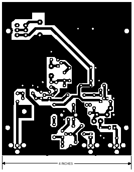
Printed Circuit:

You can use the printed circuit designed by the author, which has plenty of space for both components as well as for the battery clip, space for this subject and the island left to screw the antenna. It is possible, but make a custom PCB with minimum space required, provided that you follow the guidelines of the electrical circuit. In both cases it is advisable to use printed circuit board in place of the phenolic pertinax since the latter absorbs moisture which would cause instability of the system.

Domestic TV Transmitter PCB1

Side tracks (welding) in size. (scale 1:1)

Domestic TV Transmitter PCB

Expanded components distribution.

Notes:
  • The 4.5MHz RF transformer (T1) can be anything that fits, provided you have the internal capacitor connected to the secondary.
  • L4 must be done manually. Respect the parameters given above.
  • If used in resistor R12, to be placed on the solder side of the printed circuit between the antenna output and ground. This component must be installed whenever you use an antenna other than the internal, making a correct fit between it and the circuit.
Adjust:

To calibrate the transmitter will need a TV receiver and a signal source such as a video recorder or a camcorder. Need, moreover, a non-metallic tool to adjust the coil L4 and the transformer T1. A new 9v battery can be used for adjustments, but if calibration is difficult, try doing it with a 12v power supply. Note that during the adjustment and testing of the unit, we find that it works much better with a stable supply filtered 12 volts. If you come to the same conclusion, add a voltage input connector welding it to the appropriate points on the circuit board (instead of the battery clip).

Tune the TV receiver in an unused channel (no transmission) between 2 and 6. The TV must be connected directly to the internal antenna, an external antenna or a cable system will not work. Make sure both knobs are in the center position (at halfway) and apply power to the circuit. Adjust L4 with non-metallic tool until the TV screen goes blank (rain disappears). Then, carefully adjust L4 to achieve the best possible reception. Connect the audio outputs of a VCR and other video source to J1 and J2, if necessary operate the VCR. You should see the image on the TV screen: if so, L4 setting up the best picture possible, and if not, check the circuit board in search of an error in welds or components in the inputs. Then adjust R3 for optimum brightness and R7 for a general adjustment of video quality. You may need to make minor adjustments on L4 after adjusting R3 and R7. Finally, adjust T1 with nonmetallic tool to get the best audio possible. After that the transmitter is properly calibrated.

Domestic TV Transmitter image
View completed and mounted equipment in your cabinet

Important:

The use of these systems is regulated by law in much of the world. Before operating, we suggest that you consult a competent legal authority on the scope and restrictions of the law regarding the use of these devices. In some countries can cause illegal emissions from confiscation of equipment to the prison of the copyright holder.


read more...

Electronic Combination Lock with Auto Reset


Electronic Combination Lock

Electronic Circuits Electronic Combination Lock circuit. Electronic circuit CD4013 ICs are used. 2-3-6-9 used to hold temporary password. Change the password by modifying the electronic circuit. Electronic Circuit unscheduled work. Making simple and easy. The circuit can use it anywhere you want

Electronic Combination Lock Circuit Diagram With Parts

Electronic Combination Lock Circuit Diagram

Electronic Combination Lock PCB


read more...

Simple Mosquito Repellent

Electronic Circuit mosquito repellent circuit. Making simple and easy. Entegeresi circuit 555 is used. Wave output between 200 Hz and 62 kHz are available. 555 Entegresi by a power frequency of the buzzer, buzzer frequency is converted by the annoying sound for mosquitoes

Mosquito Repellent Circuit Diagram

Mosquito Repellent Circuit Diagram

read more...

Home Security System

This alarm circuit activates when S1 through S5 are activated. This lights LED1 and activates Q1 via IC1C and IC1D. RY1 is wired to self latch. S10 is used to reset. When key switch S1 is activated or when re-entry buttons at S6 are depressed, IC1C is deactivated until RC network R7/C3 charges.

Home Security System Circuit Diagram 


read more...

Electronic Smart Heater Controller

Minuscule circuit of the electronic heater controller presented here is built around the renowned 3-Pin Integrated Temperature Sensor LM35 (IC1) from NSC. Besides, a popular Bi Mos Op-amp CA3140 (IC2) is used to sense the status of the temperature sensor IC1, which also controls a solid-state switch formed by a high power Triac BT136(T1). Resistive type electric heater at the output of T1 turns to ON and to OFF states as instructed by the control circuit.

This gadget can be used as an efficient and safe heater in living rooms, incubators, heavy electric/electronic instrument etc. Normally, when the temperature is below a set value (Decided by multi-turn preset pot P1), voltage at the inverting input (pin2) of IC1 is lower than the level at the non-inverting terminal (pin3). So, the comparator output (at pin 6) of IC1 goes high and T1 is triggered to supply mains power to the desired heater element.

Electronic Heater Controller Circuit diagram:


Note: CA3140 (IC2) is highly sensitive to electrostatic discharge (ESD). Please follow proper IC Handling Procedures.

When the temperature increases above the set value, say 50-60 degree centigrade, the inverting pin of IC1 also goes above the non-inverting pin and hence the comparator output falls. This stops triggering of T1 preventing the mains supply from reaching the heater element. Fortunately, the threshold value is user-controllable and can be set anywhere between 0 to 100 Degree centigrade.

The circuit works off stable 9Volt dc supply, which may be derived from the mains supply using a standard ac mains adaptor (100mA at 9V) or using a traditional capacitive voltage divider assembly. You can find such power circuits elsewhere in this website.
read more...
 
Copyright © 2019 W3circuits.blogspot.com • All Rights Reserved.
back to top