Showing posts with label Hobby. Show all posts

Elegant Bathroom Mirror Lights with Motion Detector

The inspiration for this project came from the artwork shown here, prepared by my neighbor who is a carpenter. The project was nothing more than a bathroom washbasin mirror with a bunch of lamps around it. After some experiments with lightbulbs and rocker switches, I decided that it was a dangerous idea to have a rocker switch (made of obscure materials) connected to a fatal AC mains supply very close to my wife when her hands are soaked with water. However, I still cherished it, so to spice things up, I just revamped the concept and added some cool features.

Detector

Woodworking

First, the enclosure/frame is made of wood and adheres to the rules of standard mirror sizes (thanks to my neighbor). Bulb holders were screwed to the front panel of the frame, with its wires routed through the backplate of the frame. There are also some small wooden pieces to act as spacers between the backplate and the wall — not too bad!

Solder Fumes

Because I wanted to drop the simple rocker switch and also sought the assistance of an automatic switch, I decided to employ a passive infrared motion detector-based switch mechanism to drive the lightbulbs. For some reason, all of the electronics are enclosed in a separate plastic enclosure with enough wires for interconnection. Let’s make a list of early electric/electronic parts:
  • AC230V/1-W White LED Globe Bulb x20
  • PIR Motion Detector Module x1
  • Plastic Enclosure (duh!) x1
Circuit Tracks

Motion Detector


The first part of the schematic is a transformer-less DC power supply for converting the 230-V AC input to about a 16-Vdc output. This DC output is used to power the rest of the electronics, excluding the motion sensor. The very popular, yet cheap, DYP-ME003 PIR sensor module is used here for the detection of human motion. Refer to its datasheet for technical specification, calibration information, etc. Because the module has a provision to attach one light-sensitive resistor (LDR/photoresistor/CdS cell), a 5-mm standard LDR is attached to the module after a minor mod.

This drives the switch to be operational only when the detection area is sufficiently dark (the mirror lights up when one enters the darkened bathroom). For this, just detach the fresnel lens of the module, carefully solder the LDR on the vacant pads denoted as “CdS,” ensuring that it faces toward the fresnel lens, and retain the fresnel lens in front. Next, flip the module to replace the 1M (105) SMD resistor with a 100K (104) SMD resistor. Note that one end of this resistor (and one lead of the photoresistor) is linked to “trigger disable” (pin 9) of the BISS0001 IC. The other end of the resistor is tied to the 3.3-V (Vcc) rail, whereas the second lead of the photoresistor is connected with the 0-V (GND) rail.

Tail End

Elegant Bathroom Mirror Lights with Motion Detector


Lights with Motion Detector
The PIR motion detector might be tricky to implement. The light coming from the LED lightbulbs may mess with the ambient light sensor inside the motion detector module, and this may cause erroneous operation when the mirror is alive. So it is necessary to isolate the module from the light source. Not a big deal!

Author By: T.K. HAREENDRAN


read more...

Temperature Candle Using LED

LED based projects require a lot of skill and hence only experienced circuit designers try out these circuits. But there are also a few circuits in this genre that can be done by amateur electronic hobbyists. The temperature candle is one such circuit. Read on to know more about this.

LED

The hardware components that are required to build this circuit are listed below:
  • Microcontroller
  • Temperature Sensor
  • RGB LED
  • PCB
The circuit design is pretty simple. The LED is made to flicker by the microcontroller and the color is based on the ambient temperature at that point. The temperature of the room can be known by observing the color of the LED.

The temperature value is obtained in degree Celsius. This value is received as a result of pressing the reset button on the PCB. This value can also be obtained by providing power to the device. Once the device is powered up, the change in temperature is indicated. The blue LED is triggered for a temperature increase of 10 degrees. The red LED is triggered for a temperature increase of a single degree.

Suppose, the ambient temperature is 23 degrees celsius, The circuit works in such a way that the blue LED is made to blink twice and the red LED is made to blink 3 times. Soon after this, an orange colored flicker is observed as the LED goes into canfle mode.

Since through hole components are used in this circuit, it is very cheap to construct and the components can be easily soldered. The circuit also contains a jack for connecting to a Microchip Pickit 3 programmer / debugger. This reduces the complexity involved in code modification and download.

read more...

Simple Make LED light-weight Box

For beginners, it's their 1st project that offers them a lift. And so as to induce that, it's continuously necessary to create positive that the project that you just choose is basically helpful. One such project is that the RGB light-weight fader. this is often quite straightforward and may be done simply by a beginner. scan on to understand a lot of concerning this.

LED light-weight Box

Concerning twenty LEDs are needed here. begin by wiring all the LEDs and connecting it to a breadboard. this is often quite a tedious method and takes quite plenty of your time.

ensuing step is to create the ability board. Quite plenty needs to be done to drive all the LEDs employing a single PWM channel. therefore to atone for this, a multiplexer IC is employed. a couple of voltage conversions is also needed in such a case.

Simple Make LED light-weight Box

As mentioned earlier, one PWM is employed to regulate 3 totally different channels. The MSP430 is employed to modify between the various channels. this offers the impression that there are 3 individual channels. There is also some problems with the glint, however this might not be a show stopper downside.

The supply code for running the circuit is kind of sophisticated . concerning twelve totally different modes are gift here and switching between the assorted modes is finished employing a single push button.

read more...

Simple Timer Hack

Simply, the timer clocks we find in stores have to be plugged in to the electrical current to work. It becomes very difficult when you require something that works on batteries The best solution is to build yourself one. It is easy to turn an electrically operated timer into a battery operated timer.

First of all, the timer has to be disassembled. This is pretty simple. All that is needed is to remove the screws that hold the back cover in place. The timer will then split. It must be separated carefully to avoid any damage on the screen or inner controls.


Timer

Timer Hack

Once it is disassembled, the original PCB should be removed completely, in order to gain access to the full back cover. Now the space is free, the only thing available is a totally useful space that comprises of the plastic marks and walls used to set and hold the original PCB.

The plastic features can be removed by using a Dremel tool. It is highly recommended that some kind of mask or protection for eyes, nose and mouth should be used while using the Dremel tool because it produces some dust.

After clearing the space completely, it is time to add the new connections for the battery. All that is needed is a AA battery holder, which can be acquired at any electronics store, and the proper connections to feed the battery power to the timer.

read more...

Portable 12V to 250V Converter

Here are very simple and low-cost electronic circuit project for student and hobbyist. This portable 12v to 250V converter can be designed using this circuit diagram. This 12 to 250V converter is designed for portable use with a 12 V car battery. A built astabil multivibrator T1 and T2 generates a rectangular wave at a frequency of 50 Hz. As T1 and T2 drive alternative exit stage system also works in "push-pull".

When T1 lead by passing a current T3: T5 and that it engages the latter transistor connects to a half battery of 12 V secondary winding of the transformer Tr When T2 network drive, T6 transistor coupled to the battery the other half of the network adapter.

Portable 12V to 250V Converter Circuit Diagram:

Converter Circuit Diagram
 

If it is used for output stages 40 411 RCA transistors, the current through secondary winding can be up to 10 A, giving a power output of 180 watts. If you use 2N3055 transistors, power output will be about 90 watts. Since the output transistors are driven to saturation, they have very high mounted radiators.

Although circuit is simple construction and has high efficiency disadvantage is rectangular output voltage which, in the absence of a regulator is dependent on task: small loads, the output voltage is 250 V ac (not working properly for the engine speed control, light dimmers, televisions, hi-fi equipment.
read more...

Automotive Turn Flasher with lamp output Detection

Here is a circuit of a flasher which I designed for automotive use. It has a built-in function of lamp-outage detection. In normal operation, it will flash at about 1.4Hz and when a lamp goes bad, the flash-rate is doubled. The flashers faster clicking sound and the dashboard indicators faster flashing attracts the drivers attention that one of the bulbs has gone out.

Automotive Turn Flasher with lamp  output Detection:

Automotive Turn Flasher with lamp  output Detection
 
Notes
The circuit consists of two parts - the flashing unit and the lamp outage detection module. The flashing unit is built around 555 timer configured as an astable multivibrator. The resistors R12/R13 and capacitors C3/C4 sets the required frequency. Note that C3 is connected in parallel to C4 through BC547 an NPN transistor, acting as a switch. When there is positive voltage at the base of the transistor, it conducts and connects C3 to ground. C3 & C4 in parallel doubles the capacitance value i.e. 220nF + 220nF = 440nF. This capacitance value together with R12 and R13 result in frequency of about 1.4Hz.

In the lamp outage detection module, a shunt resistor (a thick wire) with a calculated minor resistance (30mΩ) is the key to detect the lamp outage. The voltage to lamps is fed thru this shunt. Hence, the shunt is connected in series to the network of the bulbs which are connected in parallel. The inverting input of the comparator U1 is also connected to the shunt. The non-inverting input is connected to a potential divider providing a reference voltage of 11.90V

NORMAL OPERATION:

Square wave between 11.89V - 12.0V at (-)ve input of U1
11.90V (reference voltage) at (+)ve input of U1

The comparator U1 compares these voltages and the output is a square wave between 0-12V. This output is rectified through diode D1 and filtered through capacitor C1. Now, we have a triangular wave form which is fed into another comparator U2.

1V (reference voltage) at the (-)ve input of U2 and
a triangular wave between 7V - 8V at (+)ve input of U2
OPERATION WITH A DEFECTIVE LAMP: OPERATION WITH A DEFECTIVE LAMP:
When a bulb is defective, there is an increase in the resistance of the bulb network hence the voltage drop across the shunt is changed. So, in this case we would have:

Square wave between 11.95V - 12.0V at (-)ve input of U1
11.90V (reference voltage) at (+)ve input of U1

The comparator U1 compares them and the output is almost zero volts. After the diode and the filter network, we finally have a few millivolts at the +input of U2 which is compared with the reference voltage, 1V. This results in low output of U2 which ultimately switches off the NPN and hence C3 is disconnected from the ground.

Now, the timing network of 555 has only C4 to work with, therefore the frequency of the oscillation is doubled. This causes the remaining bulbs to flash at doubled rate.

NOTE:
A single quad op-amp IC LM324 could also be used for building this circuit. Two of the op-amps to be used as comparators in place of U1 & U2. Another op-amp can be configured as astable oscillator in place of 555 to flash the bulbs. This astable oscillator will have two timing capacitors as used above with 555.

Source by: CirucitLead

read more...

Simple 3-in-1 Flash Light Project

Want to avoid the problem of carrying three different flashlights to perform a test? Why don’t you try integrating Ultra Violet, Infra Red and visible light together in one flashlight? Read on to know more about this.

The multi-tasking flashlight is basically composed of a metallic case, a switch, cables and connections, four 9V batteries and three different LED heads that provide the desired light beam. For the construction of this flashlight, LedEngin’s LZ4-40 is recommended. This comes with a very wide wavelength that includes infra red and ultra violet light. Distinct visible light color temperature can also be found.
Flash Light Project


Flash Light Project

The first step is to build the body of the flashlight, using an aluminum tube. Next come the drilling and cutting for switches and covers. Once the body is finished, the work on the constant current driver should be completed, adding the proper terminals for the batteries and the base for the LED heads.

Once all the power source wiring is completed and insulated with heat shrink tubing, the LED heads are assembled and connected. These are basically composed of an aluminum cap. The LED base and the power source connections come from the batteries.

read more...

Automatic fan controller

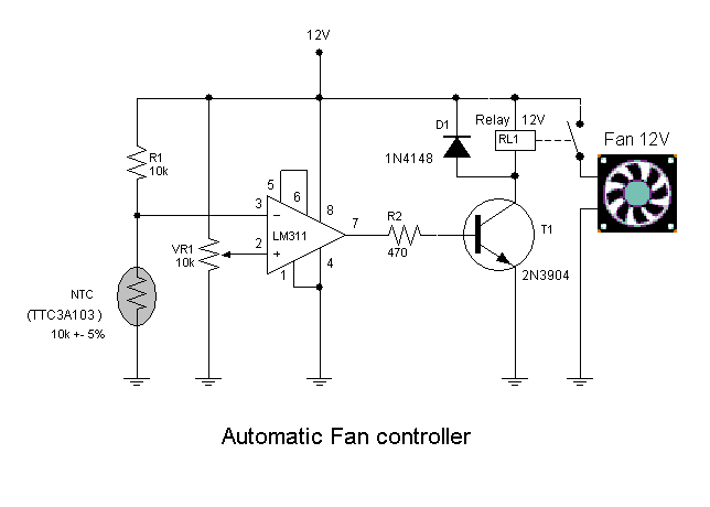
This circuit will turn on/off 12V DC fan or CPU fan when temperature above normal temperature.You can set turn on temperature by adjust VR1.

Automatic fan controller Circuit Diagram:
controller Circuit Diagram
This circuit use an NTC (Negative temperature coefficient)which is a thermistor is one in which the zero-power resistance decreases with an increase in temperature. So If temperature increate the voltage at pin 3 on LM311 will decreated .The resistance of NTC is about 10K at 25'c.

VR1 should be multi-turn potentiometer type such 10K/25 turn.
read more...

Simple Doorbell with Counter

This circuit is a doorbell with counter, that means it counts how many times the bell is triggered. It uses a chip synthesizer sound, the HT-2811 ms nothing prevents you from using another device sound generator.

Simple Doorbell with Counter Circuit Diagram:

Simple Doorbell with Counter Circuit Diagram
The HT-2811 reproduces the sound of a "ding-dong" doorbell. Besides this ic, the circuit includes a CMOS 4026 and Display Driver IC which counts the total number of visitors.

read more...

IC 555 Design Note

The popular Timer IC 555 is extensively used in short duration timing applications. IC 555 is a highly stable integrated circuit functioning as an accurate time delay generator and free running multivibrator. But one of the serious problem in 555 timer design is the false triggering of the circuit at power on or when voltage changes. The article describes how IC555 is designed perfectly to avoid false triggering.

555 IC pin functions
  • Pin1 Ground
  • Pin2 Trigger
  • Pin3 Output
  • Pin 4 Reset
  • Pin 5 Control voltage
  • Pin 6 Threshold
  • Pin 7 Discharge
  • Pin 8 Vcc

Functional aspects of pins

Trigger Pin 2

Usually pin2 of the IC is held high by a pull up resistor connected to Vcc. When a negative going pulse is applied to pin 2, the potential at pin 2 falls below 1/3 Vcc and the flip-flop switches on. This starts the timing cycle using the resistor and capacitor connected to pins 6 and 7.

Reset pin 4

Reset pin 4 can be controlled to reset the timing cycle. If pin 4 is grounded, IC will not be triggered. When pin4 becomes positive, IC becomes ready to start the timing cycle. Reset voltage is typically 0.7 volts and reset current 0.1 mA. In timer applications, reset pin should be connected to Vcc to get more than 0.7 volts.

Control Voltage pin 5

Pin5 can be used to control the working of IC by providing a DC voltage at pin5. This permits the control of the timing cycle manually or electronically. In monostable operation, the control pin5 is connected to ground through a 0.01 uF capacitor. This prevents the timing interval from being affected by AC or RF interference. In the Astable mode, by applying a variable DC voltage at pin 5 can change the output pulses to FM or PWM.

Threshold pin 6 and Discharge pin 7

These two inputs are used to connect the timing components- Resistor and Capacitor. The threshold comparator inside the IC is referenced at 2/3 Vcc and the trigger comparator is referenced at 1/3 Vcc. These two comparators control the internal Flip-Flop of the circuit to give High or Low output at pin 3.When a negative going pulse is applied to pin 2, the potential at pin2 drops below 1/3 Vcc and the trigger comparator switches on the Flip-Flop. This turns the output high. The timing comparator then charges through the timing resistor and the voltage in the timing capacitor increases to 2/3 Vcc.( The time delay depends on the value of the resistor and capacitor.

That is, higher values, higher time).When the voltage level in the capacitor increases above 2/3 Vcc, the threshold comparator resets the Flip-Flop and the output turns low. Capacitor then discharges through pin 7.Once triggered, the IC will not responds to further triggering until the timing cycle is completed. The time delay period is calculated using the formula T= 1.1 Ct Rt. Where Ct is the value of Capacitor in PF and Rt is the value of Resistor in Ohms. Time is in Seconds.

How to eliminate false triggering?


The circuit diagram shown below is the simple monostable using IC 555. To eliminate the false triggering resistor R1 and Capacitor C1 are connected to the reset pin 4 of the IC. So the reset pin is always high even if the supply voltage changes. Moreover capacitor C3 connected close to the Vcc pin 8 acts as a buffer to maintain stable supply voltage to pin 8. Using this design, it is easy to avoid false triggering to a certain extent.

555 Monostable circuit 

555 Monostable circuit
 
A ready recknor to select timing resistor and capacitor

Monostable circuit
 

Theoretically long interval is possible with IC 555,but in practical conditions, it is difficult to get more than 3 minutes. If low leakage Tantalum capacitor is used, this can be increased to 5 minutes or more. If the value of the timing capacitor is too high above 470 uF, charging time will be prolonged which will upset the timing cycle and the output remains high even after the desired time is over.

read more...

Power-Back Surge Protection

Power-Back Surge Protector is a simple yet effective solution for protecting your valuable and sensitive electric/electronic systems. Power-Back Surge typically occurs when power returns after a power-cut (black out) and connected equipments receives a surge of electricity at an over-voltage level, which can be very damaging. Usually, power-back surges are created by the utility, when it restores supply at an above normal voltage level inorder to compensate for the demand as connected equipment restarts at the same time. The author took this little circuit personally to protect numerous lab equipments including his fave DSO!

Power-Back Surge Protection Circuit Diagram:

Power-Back Surge Protection Circuit Diagram
 
The circuit is designed to be constructed in a small module structure with an onboard electromagnetic relay as the primary switching device. The design is centered around (again) the famed 555 timer, wired as a bi-polar latch switch with its two comparator inputs tied together and biased at 1/2 Vcc through a resistive-potential divider. Since the threshold comparator will trip at 2/3 Vcc and the trigger comparator will trip at 1/3 Vcc, the bias provided by the resistors are centered within the comparators trip limits. The module does need a source of external power for operation, and so a “clean” 5v dc supply is preferred here as the power supply for the entire circuit.

Protection Circuit Diagram

However, note that the onboard miniature relay cannot drive grid-supply powered “goliath” loads without the help of an external heavy-duty switching relay. It is better to use a T90 type (5v dc) heavy-duty relay as the external relay, because the type can handle too much power efficiently.

Working of the circuit is very simple. Initially when the circuit is powered up or when power supply is resumed, the relay remains in the de-energized state. This prevents the power supply from reaching to the connected load. When the push-to-on switch (a good quality momentary push button switch required) is depressed, the circuit turns to active mode, relay is energized, and hence power supply is extended to the connected load. The red LED in the circuit is the “power in” status indicator, and the green LED is the “power out” status indicator.

Surge Protection Circuit Diagram

Author used an “O/E/N” pcb relay (part # 46-05-2CE) in the prototype, and a “Tyco” T90 pcb relay (part# T90N5D12-5) as the optional external relay. Photograph of the initial prototype with some components soldered at the bottom side of the perfboard (however, without the red indicator, push button switch, and headers) is shown below. Sorry have to be the potato picture as the finished system is in use now!

Author By: T.K. HAREENDRAN

read more...

Protection For Your Electrical Appliances

This is a project of Protection For Your Electrical Appliances Circuit Diagram. Here is a very low-cost circuit to save your electrically operated appliances, such as tv, tape recorder, refrigerator, and other instruments during sudden tripping and resumption of mains supply. Appliances like refrigerators and air-conditioners are more prone to damage due to such conditions. The simple circuit given here switches off the mains supply to the load as soon as the power trips. The supply can be resumed only by manual intervention. Thus, the supply may be switched on only after it has stabilised.

 Protection For Your Electrical Appliances Circuit Diagram:

 Electrical Appliances Circuit Diagram

The circuit comprises a step-down transformer followed by a full-wave rectifier and smoothing capacitor C1 which acts as a supply source for relay rl1. Initially, when the circuit is switched on, the power supply path to the step-down transformer X1 as well as the load is incomplete, as the relay is in de-energised state. To energise the relay, press switch S1 for a short duration. This completes the path for the supply to transformer X1 as also the load via closed contacts of switch S1. Meanwhile, the supply to relay becomes available and it gets energised to provide a parallel path for the supply to the transformer as well as the load.

If there is any interruption in the power supply, the supply to the transformer is not available and the relay de-energises. Thus, once the supply is interrupted even for a brief period, the relay is de-energised and you have to press switch S1 momentarily (when the supply resumes) to make it available to the load. Very short duration (say, 1 to 5 milliseconds) interruptions or fluctuations will not affect the circuit because of presence of large value capacitor which has to discharge via the relay coil. Thus the circuit provides suitable safety against erratic power supply conditions.
Author : MALAY BANERJEE

read more...

How to Make your own Breadboard

Breadboard

Often we do not have the opportunity or the money to keep our hobby, sometimes we lack tools, but always there is a knack for everything, is what we see here in this article was originally published at indestructible. He teaches you how to make your own breadboard using scrap old computers, in fact it uses sockets IDE cable. The breadboard makes life easier for those who like to create electronic circuits, and can only plug components without using solder.

own Breadboard

read more...

Automatic Water Tank Filler Schematic

This circuit has been very useful in filling a header tank for a reticulated water supply on a farm. Eight troughs are supplied in different paddocks where a lack of water would have serious consequences for the stock. In the past, the tank had been filled daily by a time clock which was not successful. During hot weather, the stock would empty the tank on a regular basis and then be without water for several hours or the tank would overflow and flood the area if the weather was wet and the cattle did not drink much.1.

Automatic Water Tank Filler Schematic Circuit Diagram:

Automatic Water Tank Filler

The circuit described has been used to maintain the level of water in the header tank within prescribed limits. It controls a 3HP submersible bore pump which has a high starting current, necessitating a solid-state relay sufficient to take the starting load. Two Darlington transistors, Q1 & Q3, in conjunction with Q2 & Q4, are connected to the upper and lower water sensors in the tank. Q2 & Q4 have a common 5.6kO load resistor and function as a NOR gate. The output of the NOR gate drives Q5 which activates relay RLY1.

 Initially, when the water level is low, both sensors will be open-circuit, the NOR gate output will be high and the relay will be turned on. This causes the normally closed (NC) contacts of the relay to open and disconnect the lower sensor. However, the upper sensor will still be open circuit and the NOR gate output will be high, keeping the relay closed. The normally open (NO) contact of the relay will be closed to operate the solid-state relay RLY2 to run the pump.

This state continues until the water reaches the top sensor which will then drop the output from the NOR gate to 0V. The disables relay RLY1 and the pump is stopped. In practice the upper level sensor is just below the overflow from the tank and the lower sensor about half way up the tank. The sensor contacts are simply two stainless steel screws about 25mm apart and screwed through the poly tank walls. The wiring junctions on the side of the tank are protected by neutral-cure silicone sealant.
read more...

Build a Homemade Melody Door Bell

This is the Simple Homemade Melody Door Bell Circuit Diagram. In most of the homes the door bells are conventional ding-dong type. Most of us don’t like its sound. Due to mechanical moving parts with spring mechanism its long term durability is questionable. I had also one such door bell in my home. After a period of time its performance deteriorates and one time it becomes completely intolerable because of its noisy irritating sound.

Melody Door Bell

The new types of door bells available in market are bird sound door bell. They are costly. and even I didn’t like it because of its high frequency and high volume sound output.  

Simple Homemade Melody Door Bell Circuit Diagram:

Door Bell

So the idea came into my mind that why not to build a very simple door bell with few components that gives nice melodious output and that is at the less cost also. So I build this door bell with all the items available in home. Let us see how I have made it.

Description

  • First collect the required components
  • Transformer – 230 V to 18 V@500 mA
  • Diode bridge or 4 diodes – 1N4004
  • Capacitors – 1000 µF, 0.1 µF
  • Resistors - 560Ω
  • Voltage regulator ICs – LM7805, LM7812
  • Relay – 12 V 1 C/O
  • Transistor – 2N2222A
  • 8Ω speaker
  • Melody generator IC UM66


Now build the circuit on general purpose PCB. (See the circuit diagram tab for the doorbell circuit)

Circuit description:

  • 230 VAC is applied to primary of transformer with bell switch in between as shown
  • The secondary of transformer is connected to AC input terminals of diode bridge
  • A 1000 µF capacitor is connected across rectified output terminals of diode bridge
  • This output is given as input to both voltage regulator chips 7812 and 7805
  • The output of 7812 IC drives relay coil directly. A filter capacitor of 0.1 µF is connected across it.
  • The output of 7805 is given to common terminal of relay
  • The second normally open terminal of relay is connected to input of UM66 through voltage divider network made up of resistors R1 and R2
  • The output of UM66 drives 8Ω speaker through NPN type transistor Q1

Circuit operation:

  • When bell switch is pressed and hold for some time (2-3 sec) the AC supply is given to primary of transformer
  • The diode bridge rectifies AC supply available from secondary. Capacitor C1 filters it out and finally 7812 will generate 12 V and 7805 will generate 5 V
  • As relay gets 12 V, it energise and switches ON
  • So common terminal gets connected to normally open terminal and 5 V supply is given to UM66 through voltage divider. Due to same values of R1 and R2 2.5 V is given to UM66
  • UM66 generates musical sound output that is amplified by Q1 so that musical output is audible through speaker


Here is the photograph of the circuit that is completely housed in a plastic box. The plastic box is hanged on the wall at the place where wire connections for door bell are given. The transformer primary inputs are taken out of box and connected with these wires as shown in photograph given below.

Homemade Melody Door Bell

Now when external door bell switch is pressed and hold for 2-3 seconds a musical – melody sound is produced from bell.


read more...

Lighting Garden with Solar Energy

Here is a very simple and effective circuit Project of Lighting Garden with Solar Energy Circuit Diagram. This is an economic circuit of a mini solar lighting system, solar panel 6V/2W is used to charge a rechargeable 4V/800mAh through a current limiting circuit load that uses a LM317T adjustable regulator 3 pin (IC1). Assuming a sunny day 6 hours, a panel will enviarr 2 watts for approximately 900mAh battery. The current can be reduced by increasing the value of R1, for example, 8.2 to 10 ohms ohms.

Lighting Garden with Solar Energy Circuit Diagram:

Solar Energy Circuit Diagram


Specification of a typical solar panel:

6V/2W:Maximum power (Pm):
2WWorking Voltage (Vmp):
9VWorking Current (Imp):
220mAOpen Circuit Voltage (Voc):
10.5VPower Tolerance: -3% to 5%
read more...

Simple Garage Door Closing Circuit Just using Relays

Because I’m old school, I wanted to build a Garage Door Closing circuit without relying on integrated configurations (555 timer etc) to keep it simplistic. The circuit closes the garage door after two minutes with C3 and four minutes with the addition of C2. The timer relay is surprisingly accurate (+/- five seconds). Another feature is to ensure that the garage door actually did close, such as if it’s stopped mid-operation by the user.

 Relays

S3 (magnetic N.C.) is located at the garage door and activates the circuit when the garage door opens.
RL1 is the reset timer. It’s maintained in the “on” position for two minutes by C3 while the trigger capacitor, C4, is charged. RL2 is the conduit, directing C4 to either RL3 or R1 to ground when off. Purpose of R1 is to prevent arching across contacts and a fast discharge. RL3’s contacts are connected to the Garage Door’s Momentary Switch and is sustained “on”  for a half second by C5.

Circuit Just using Relays
When C3 discharges to the cutoff voltage of RL1, it turns off and resets. C4 charges C5, which turns on RL3 and initiates the garage door. Because C4 does not have the time to fully discharge, it should be at least three times the value of C5. If it does not close, RL1 in countdown mode will reset and open the door. When it resets again, the door will close.

Turning off the circuit, C1 maintains RL1 “on” slightly longer to ensure that RL2 is set to discharge C4 to R1. If this is not done and C4 is not discharged, the garage door will not open until it discharges naturally and falls below the trigger voltage for RL3.  The circuit would be useless for several days.

Notes:
  • Time delay of RL1 after reset drops 15 seconds because of the short charge time.
  • To boost RL3 to a one-second delay, increase C5 to 1000uF.
  • D2, D3, and D4 isolate the crucial sections of the circuit.
  • Relays do not turn off at the same rate. I conducted a test by tripping the circuit on and off at a high rate and discovered the possibility of C4 turning on RL3. The addition of C1 solved this.
read more...

Build Improvised Fan Grills

Making your own grill for your fans would be a lot easier and cheaper. You could use all materials that can be found in your home.

Improvised Fan Grills

Your main component would be your old fan, removed its metal ring and you can now measure the desired length or size of grid that you will be needed. Cut the grid across so it will be easier to cut, then place it in the tower and use the same screw you removed in the fan.

Improvised Fan Grills

Now you can put the grid holding fan back in its place. Clean up and you can now use your very own fan grills that cost almost nothing but your patience.
read more...

Build LED Clock Using PIC 11

Now you'll be able to perpetually grasp the precise time. With this style you'll be able to have an atomic clock in your area. Isn’t that great? scan on to grasp additional.

Build LED Clock Using PIC 11

First of all, it's not regarding any radioactive components here. this can be regarding building a clock show that may get the time from the DCFF77 facilities in Frankfurt, Germany.All that's required may be a clock LED show, DCFF77 receiver, and a microcontroller at the side of the mandatory connections.

Basically, the project permits a sign that's sent by the DCFF77 radio station to be decoded. After that. the microcontroller method it and sends it to the LED show to indicate the precise time. there's no got to build a sign receiver, an honest quality receiver may be bought on the net for a coffee worth.

Once everything has been set within the affiliation board the PIC supply code ought to be developed. The orientation of the antenna ought to be perpendicular to Frankfurt. it'll receive signal if it's among 2000 miles from town. If there's a sign, the amount on the clock LED show can blink during a constant rhytm. When a full cycle of binary pulses is received, the clock can show the precise time.
read more...

Easy Build Soldering Iron Project

The article can guide you on how a soldering iron is made on your own. Moreover, it'll not value you an excessive amount of. scan on to grasp a lot of.

Easy Build Soldering Iron Project

The soldering iron could be a battery operated one. A relay is added in order that the battery is turned off once the adaptor is plugged to a socket. A soldering iron is needed to solder the battery holder, switches and also the wires. If a soldering iron isn't offered, the wires is twisted along and lined using insulation tape. however this could not be the simplest approach.

The hardware needed for this project is listed below:
Soldering iron tip
6V battery holder
A Switch
Wooden box
E-10 lamp base
Soldering iron
Solder

Firstly, the look ought to be created. Since the iron will hande solely a current of regarding one.7 amps, parts that take plenty of current shouldn't be used. All the parts are mounted in an exceedingly wood box. This makes it moveable and simple to use. In case this must be reworked into a plug in iron, all that must be done is to switch the battery pack with a six volt DC wall wart.

Soldering Iron Project

That's it. The soldering iron is currently able to be used. The circuit is changed to suit any specific necessities.
read more...
 
Copyright © 2019 W3circuits.blogspot.com • All Rights Reserved.
back to top