Showing posts with label Security. Show all posts

Dual Sensor 555 Timer Alarm

This electronic circuit project is a very simple alarm circuit that is based on the 555 timer integrated circuit. This alarm circuit can be used with many types of sensors like : light or temperature sensors. As you can see below some types of sensors that can be connected at this type of alarm circuit ( darkness , light , cold and heat sensor ).

Dual Sensor 555 Timer Alarm Circuit Diagram:
 
Alarm Circuit Diagram

If the sensor detects that the temperature or light is outside of the desired range the alarm will be activated .By turning the  potentiometer from the base of Q1  you will modify the sensibility of the sensor . When the alarm is activated the Q2 transistor acts as an audio amplifier and speaker driver for the 16 ohms speaker .

This alarm circuit require a 12 volts DC power supply circuit:

555 Timer Alarm Circuit Diagram
 
read more...

Simple Midnight Security Light

Most thefts happen after midnight hours when people enter the second phase of sleep called ‘paradoxical’ sleep. Here is an energy-saving circuit that causes the thieves to abort the theft attempt by lighting up the possible sites of intrusion (such as kitchen or backyard of your house) at around 1:00 am. It automatically resets in the morning. The circuit is fully automatic and uses a CMOS IC CD 4060 to get the desired time delay.

Light-dependent resistor LDR1 controls reset pin 12 of IC1 for its automatic action. During day time, the low resistance of LDR1 makes pin 12 of IC1 ‘high,’ so it doesn’t oscillate. After sunset, the high resistance of LDR1 makes pin 12 of IC1 ‘low’ and it starts oscillating, which is indicated by the fashing of LED2 connected to pin 7 of IC1. The values of oscillator components (resistors R1 and R2 and capacitor C4) are chosen such that output pin 3 of IC1 goes ‘high’ after seven hours, i.e., around 1 am.

Midnight Security Light Circuit Diagram:

Light Circuit Diagram

This high output drives triac 1 (BT136) through D5 and R3. Bulb L1 connected between the phase line and M2 terminal of triac 1 turns on when the gate of triac 1 gets the trigger voltage from pin 3 of IC1. It remains ‘on’ until pin 12 of IC1 becomes high again in the morning. Capacitors C1 and C3 act as power reserves, so IC1 keeps oscillating even if there is power interruption for a few seconds. Capacitor C2 keeps trigger pin 12 of IC1 high during day time, so slight changes in light intensity don’t affect the circuit.

Using preset P1 you can adjust the sensitivity of LDR1. Power supply to the circuit is derived from a step-down transformer T1 (230V AC primary to 0-9V, 300mA secondary), rectifed by a full-wave rectifer comprising diodes D1 through D4 and fltered by capacitor C1. Assemble the circuit on a general-purpose PCB with adequate spacing between the components. Sleeve the exposed leads of the components. Using switch S1 you can turn on the lamp manually. Enclose the unit in a plastic case and mount at a location that allows adequate daylight.

Caution:
Since the circuit uses 230V AC, many of its points are at AC mains voltage. It could give you lethal shock if you are not careful. So if you don’t know much about working with line voltages, do not attempt to construct this circuit. We will not be responsible for any kind of resulting loss or damage. link

read more...

Simple Security Monitor

A remote listening circuit. The area to be monitored is connected via a cable and allows remote audio listening.

Simple Security Monitor Circuit Diagram:

Circuit Diagram

Notes:
You can use this in your garden and listen for any unusual sounds, or maybe just wildlife noises. If you have a car parked in a remote location, the microphone will also pick up any sounds od activity in this area. The cable may be visible or hidden, screened cable is not necessary and you can use bellwire or speaker cable if desired.

Circuit Description:
Starting from the right hand side, the power supply. I have used 12V as a standard power supply voltage, or a 12V car battery may be used. The circuit is in two halves, a remote microphone preamp, and an audio amplifier based around the National Semiconductor LM386 audio amplifier.

The remote preamp uses an ECM microphone to monitor sound. A direct coupled 2 stage amplifier built around Q1 and Q2 amplify the weak microphone signal. Preset resistor R2 acts as a gain control, and C1 provides some high frequency roll off to the overall audio response. Q1 is run at a low collector current for a high signal to noise ratio, whilst Q2 collector is biased to around half the supply voltage for maximum dynamic range. The power supply for this preamp is fed via R10 and R6 from the 12V supply. C4 ensures that the preamp power supply is decoupled and no ac voltages are present on the power lines. The amplified audio output from Q2 collector is fed onto the supply lines via C6 a 220u capacitor. The output impedance of Q2 is low, hence the relatively high value of C6. C6 also has a second purpose of letting the output audio signals pass, whilst blocking the dc voltage of the power supply.

At the opposite end, C7 a 10u capacitor, brings home the amplified audio to the listening location. The signal is first further amplifier by a x10 voltage gain amplified using the TL071. C8, a 22p capacitor again rolls off some high frequency response above 100kHz. This is necessary as long wires may pick up a little radio interference. After amplification by the op-amp, the audio is finally passed to the LM386 audio amplifier. R14 acts as volume control. R13 and C12 prevent possible instability in the LM386 and are recommended by the manufacturer. Audio output is around 1 watt into an 8 ohm loudspeaker, distortion about 0.2%. If preferred headphones could be used, although I'd recommend a series resistor of the same value impedance as the headphones.
read more...

1-10 Minute Auto Turn Off with 555 IC

This is a simple and low-cost automatic turn-off electronic circuit diagram; this circuit provides an automatic turn-off feature after a time that can be set from 1 minute to 10 minutes by the 470k pot.

Circuit Diagram:

circuit-diagram


read more...

Fire Alarm With Thermistor

Small and simple unit, Can be used for Home-Security purpose. In this fire alarm circuit, a Thermistor works as the heat sensor. When temperature increases, its resistance decreases, and vice versa. At normal temperature, the resistance of the Thermistor (TH1) is approximately 10 kilo-ohms, which reduces to a few ohms as the temperature increases beyond 100 C. The circuit uses readily available components and can be easily constructed on any general-purpose PCB.

Fire Alarm Using Thermistor Circuit diagram:

Fire Alarm Circuit diagram


Circuit Operation:

Timer IC NE555 (IC1) is wired as an astable multivibrator oscillating in audio frequency band. Switching transistors Q1 and Q2 drive multivibrator IC1. The output of IC1 is connected to NPN transistor Q3, which drives the loudspeaker (SPKR) to generate sound. The frequency of IC1 depends on the values of resistors R6, R7 and capacitor C2. When Thermistor TH1 becomes hot, it provides a low-resistance path to extend positive voltage to the base of transistor Q1 via diode D2 and resistor R3. Capacitor C1 charges up to the positive voltage and increases the ‘on’ time of alarm. 

The higher the value of capacitor C1, the higher the forward voltage applied to the base of transistor Q1. Since the collector of transistor Q1 is connected to the base of transistor Q2, transistor Q2 provides positive voltage to reset pin 4 of IC1. R5 is used such that IC1 remains inactive in the absence of positive voltage. D2 stops discharging of capacitor C1 when the Thermistor connected to the positive supply cools down and provides a high-resistance (10k) path. It also stops the conduction of Q1. To prevent the Thermistor from melting, wrap it up in mica tape. The circuit works off a 6V-12V regulated power supply. D1 is used to indicate that power to the circuit is switched on.Link

Parts:
R1 470R
R2 470R
R3 33K
R4 560R
R5 470R
R6 47K
R7 2.2K
R8 470R
C1 10uF-16V
C2 0.04uF-63V
C3 0.01uF-63V
Q1 BC548
Q2 BC558
Q3 SL100B
D1 Red Led
D2 1N4001
IC1 NE555
SPKR 1W-8R
TH1 Thermistor-10K


read more...

Impact Sensor Uses Piezoelectric Device

Here is simple and low-cost Electronic Circuit Project of Impact Sensor Uses Piezoelectric Device. This circuit provides a low-cost alternative for solid-state general-purpose impact sensing. The circuit uses a standard piezoelectric device (PZT) to detect a mechanical shock or vibration in its vicinity (see the Figure 1).

The output of IC1, and LM555 monostable, initially is low. When an impact flexes the PZT, it generates a voltage. The base of transistor T1 is biased using the PZT, so the transistor amplifies the sensor signal, which triggers IC1’s input (pin 2) and changes the IC’s state.

Circuit Diagram:

Sensor Circuit Diagram

 Figure 1. When the piezoelectric device (PZT) detects a mechanical impact, it emits a signal that triggers the monostable (IC1), which in turn controls the output of the dual LED/phototransistor opto-coupler (IC2).

IC1’s output (pin 3) goes high for a finite time determined by the values of timing components R4 and C3. IC1’s output is routed to the inputs (pin 2 and pin 3) of IC2, a dual-LED and phototransistor opto-coupler in an eight-pin plastic dual-inline package (TLP621-2).

When IC1’s output is low, IC2’s first LED (across pins 1 and 2) lights and activates the first phototransistor (across pins 7 and 8). When the monostable’s output goes high, the first LED goes out and the second LED (across pins 3 and 4) lights, switching on the second phototransistor. The result is a solid-state dual-mode output (N/C and N/O) from IC2 that can be interfaced with an external circuit. You may need to alter the values of R5 and R6 in some applications to optimize the switching in IC2.

After constructing the circuit on a Veroboard, enclose it in a suitable ABS cabinet. Then connect the PZT to the circuit using a short length of shielded cable. Glue a rounded rubber washer on the face plate of the piezo element and attach it to the required surface with the washer facing the surface so the PZT can flex to detect impacts.


read more...

Simple But Digital Electronic Lock

This Electronic Circuit Project of simple but digital electronic Lock circuit. The digital lock shown below uses 4 common logic ICs to allow controlling a relay by entering a 4 digit number on a keypad. The first 4 outputs from the CD4017 decade counter (pins 3,2,4,7) are gated together with 4 digits from a keypad so that as the keys are depressed in the correct order, the counter will advance.

 As each correct key is pressed, a low level appears at the output of the dual NAND gate producing a high level at the output of the 8 input NAND at pin 13. The momentary high level from pin 13 activates a one shot circuit which applies an approximate 80 millisecond positive going pulse to the clock line (pin 14) of the decade counter which advances it one count on the rising edge.

A second monostable, one shot circuit is used to generate an approximate 40 millisecond positive going pulse which is applied to the common point of the keypad so that the appropriate NAND gate will see two logic high levels when the correct key is pressed (one from the counter and the other from the key).

Digital Electronic Lock Circuit Diagram:

Electronic Circuit Diagram:


The inverted clock pulse (negative going) at pin 12 of the 74C14 and the positive going keypad pulse at pin 6 are gated together using two diodes as an AND gate (shown in lower right corner). The output at the junction of the diodes will be positive in the event a wrong key is pressed and will reset the counter. When a correct key is pressed, outputs will be present from both monostable circuits (clock and keypad) causing the reset line to remain low and allowing the counter to advance.

However, since the keypad pulse begins slightly before the clock, a 0.1uF capacitor is connected to the reset line to delay the reset until the inverted clock arrives. The values are not critical and various other timing schemes could be used but the clock signal should be slightly longer than the keypad pulse so that the clock signal can mask out the keypad and avoid resetting the counter in the event the clock pulse ends before the keypad pulse. The fifth output of the counter is on pin 10, so that after four correct key entries have been made, pin 10 will move to a high level and can be used to activate a relay, illuminate an LED, ect.

At this point, the lock can be reset simply by pressing any key. The circuit can be extended with additional gates (one more CD4011) to accept up to a 8 digit code. The 4017 counting order is 3 2 4 7 10 1 5 6 9 11 so that the first 8 outputs are connected to the NAND gates and pin 9 would be used to drive the relay or light. The 4 additional NAND gate outputs would connect to the 4 remaining inputs of the CD4068 (pins 9,10,11,12). The circuit will operate from 3 to 12 volts on 4000 series CMOS but only 6 volts or less if 74HC parts are used. The circuit draws very little current (about 165 microamps) so it could be powered for several months on 4 AA batteries assuming only intermittent use of the relay.


read more...

Simple and Low-cost Gated Alarm

This Electronic Circuit Project build easy, simple and low-cost this circuit project of gated alarm. The circuit shown here employs just four components and a piezo sounder and is unlikely to be out-done for simplicity. While it does not offer the most powerful output, it is likely to be adequate for many applications.

Gated Alarm Circuit Diagram:

Alarm Circuit Diagram

A dual CMOS timer IC type 7556 is used for the purpose, with each of its two halves being wired as a simple astable oscillator (a standard 556 IC will not work in this circuit, nor will two standard 555’s). Note that the CMOS7556 is supplied by many different manufacturers, each using their own type code prefix and suffix. The relevant Texas Instruments product, for instance, will be marked ‘TLC556CN’. The circuit configuration used here is seldom seen, due probably to the inability of this oscillator to be more than lightly loaded without disturbing the timing. However, it is particularly useful for high impedance logic inputs, since it provides a simple means of obtaining a square wave with 1:1 mark-space ratio, which the ‘orthodox’ configuration does not so easily provide.

IC1.A is a slow oscillator which is enabled when reset pin 4 is taken High, and inhibited when it is taken Low. Out-put pin 5 of IC1.A pulses audio oscillator IC1.B, which is similarly enabled when reset pin 10 is taken High, and inhibited when it is taken Low.

In order to simplify oscillator IC1.B, piezo sounder X1 doubles as both timing capacitor and sounder. This is possible because a passive piezo sounder typically has a capacitance of a few tens of nanofarads, although this may vary greatly. As the capacitor-sounder charges and discharges, so a tone is emitted. The value of resistor R2 needs to be selected so as to find the resonant frequency of the piezo sounder, and with this its maximum volume. The circuit will operate off any sup-ply voltage between 2 V and 18 V. A satisfactory output will be obtained at relatively high supply voltages, but do not exceed 18 V.


read more...

Doorbell Control Porch Light Using Timer IC (NE555)

This doorbell control porch light using timer ic (ne555),can be used in doorbell in order to get indication of porch light with door alarm if any one rings the door bell.

Doorbell Control Porch Light Circuit Diagram:

Doorbell Control Porch Light Circuit Diagram:

The circuit of doorbell control porch light is build around timer IC NE555 (IC2) and is here used as astable multivibrator. The output at pin 3 goes high of IC1 when trigger is given to pin 2 from power supply. Here transistor T1 is used as relay driver transistor which energized relay when output from pin 3 of IC1 is high. After relay energized AC current flow via N/O terminal and switch on the porch light.

Triac1 with Diac1 hear is used for switch in order to glow porch light during night and switch it off at day with the help of preset VR1 and LDR1.

Note:- Here the power source of 230V AC is replaced by 110V with replacing transformer having primary 110V and secondary 12V. Rest of the circuit  of door bell controll porch light is same.

PARTS LIST:

Resistors (all ¼-watt, ± 5% Carbon)
R1 = 1 MΩ
R2 = 10 KΩ
R3 = 470 Ω
VR1 = 100 KΩ

Capacitors
C1 = 1000 µF/25V
C2 = 22 µF/25V

Semiconductors
IC1 = NE555 (Timer IC)
T1 = BC548
DIAC1 = DB-3
TRIAC1 = BT136
D1, D2 = 1N4001

Miscellaneous

SW1 PUSH-TO-ON DPST (Double Pole Single Switch) Switch
B1 = Porch Light Bulb 100W
X1 = 230V AC primary to secondary 0-12V, 250MA secondary transformer
RL1­ = 12V, 200 Ω 1C/O relay


read more...

Safety Control Two Buttons

In industry there are machines type presses that allow their operation only if the operator's hands are positioned above two buttons that give the consent only if pressed both.

Unfortunately, in some cases there were workers to have a free hand have decided to keep pressing one of two buttons to button pressed inserting a toothpick holding it so stuck simulating the " crushed " the hand.

So happened an accident and from there it became mandatory to provide that these machines in addition to having the two buttons had also a circuit that sees whether a button pressed for more than one / two seconds only while the other is still open, doff his consent also if the second button was pressed .

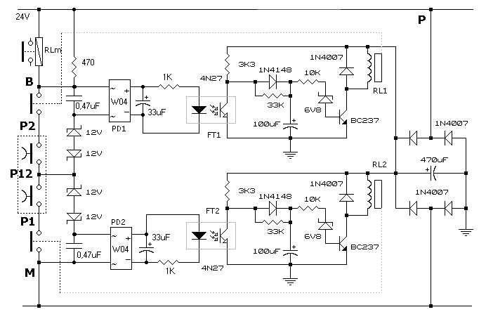
Safety Control Two Buttons Circuit Diagram:

Buttons Circuit Diagram

The circuit providing for three diode bridges , PD1 and PD2 and the group formed by four 1N4007 diodes , can run on a system is a 24V AC or 24V continuous .

When the circuit is subjected to voltage 24V and the buttons are open the photo - couplers FT1 and FT2 are disabled and that the relative transistors are blocked and do not affect the rest of the circuit. It follows that the BC237 which control the relays RL1 and RL2 can polarize through the network 3k3 , 1N4148 diode , 10K resistor and zener diode 6V8 . The relays are normally energized and will therefore closed contacts in series with the two buttons P1 and P2.

Under these conditions, if you tap P1 and P2 together energizes the relay machine RLM giving your consent to the normal operation.

If however , for any reason , one of the two buttons is pressed or remains alone for more than a couple of seconds , one of the two relay de-energizes and opens the series of links P1 , P2 and RLM inhibiting the operation of the machine even if you tap the button remained open .

In fact, suppose that P1 and P2 is pressed alone no: in the bridge of diodes PD1 current will flow in the diode as well as the photo - coupler FT1. The transitional FT1 saturated leading to mass through the positive 33K of capacity by 100 uF that after a few seconds’ drops below the 6V8 and the BC237 is cut off by de-energizing the relay RL1. Pressing P2 also now the series is interrupted and RLM can never excite. The same is true of course also redoing the same reasoning relative to P2.

Circuit Diagram

Circuit Diagram Image

If you want to further increase security, you can add a relay in parallel with each relay and put in series with the contact of RLM with the two contacts so I added a double safety switch it off even when it was only one relay to open his contact while the other to a fault remains with the contact closed. See additional relay

Procedures for Entry :


Electronic Circuit Diagram

I remind everyone that the devices are certified and can be used for security apparatuses, my project are supposed to be an example to the qualification and amateur.

The machines are subject to the certified UNI EN ISO 13849-1 (formerly EN 954-1) and UNI EN ISO 13851 (ex UNI EN 574) - Safety device with both hands.


read more...

Home Security System

This alarm circuit activates when S1 through S5 are activated. This lights LED1 and activates Q1 via IC1C and IC1D. RY1 is wired to self latch. S10 is used to reset. When key switch S1 is activated or when re-entry buttons at S6 are depressed, IC1C is deactivated until RC network R7/C3 charges.

Home Security System Circuit Diagram 


read more...

Simple Tiny Door Guard

This simple Door Chime protects the door and gives a loud Alarm tone when there is an attempt of theft. The circuit is too simple and battery operated. A Normally Closed (NC) reed switch and magnet is used to trigger the circuit. Alarm generator is the popular ROM IC UM 3561. This 8 pin IC has an inbuilt oscillator to generate 4 siren tones like, Ambulance siren, Police siren, Fire brigade siren and Gun sound. The different tones can be selected using its pin 6 connected to VCC, Ground or not connected. Frequency of oscillation is determined by the 220K resistor connected to the pins 7 and 8 of the IC.UM 3561 is the low power IC and its maximum voltage rating is 3 volts. So Zener diode ZD is used to give 3 volts supply to IC. Medium power NPN transistor T1 amplifies the output pulses from IC1 to a loud siren.

Tiny Door Guard Circuit diagram:


Magnet can be a small sized one that is to be fixed in the door using double sided adhesive tape. Fix the circuit board in the door frame. Fix Reed switch in the door frame, very close to the door. So that, when the door is closed, the magnet will pull the contacts of the reed switch to break supply to the IC. When the door opens, contacts of the reed switch make contact and IC gets power to give alarm.
read more...
 
Copyright © 2019 W3circuits.blogspot.com • All Rights Reserved.
back to top