Showing posts with label Infrared (IR). Show all posts

Simple Long-Range IR Transmitter

Most of the IR remotes work reliably within a range of 5 metres. The circuit complexity increases if you design a long range IR transmitter for reliable operation over a longer range, say, 10 metres. To double the range from 5 metres to 10 metres, you need to increase the transmitted power four times.

If you wish to realise a highly directional IR beam (very narrow beam), you can suitably use an IR laser pointer as the IR signal source. The laser pointer is readily available in the market. However, with a very narrow beam from the laser pointer, you have to take extra care, lest a small jerk to the gadget may change the beam orientation and cause loss of contact.

Long range IR transmitter

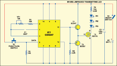
Here is a simple circuit that will give you a pretty long range. It uses three infrared transmitting LEDs (IR1 through IR3) in series to increase the radiated power. Further, to increase the directivity and so also the power density, you may assemble the IR LEDs inside the reflector of a torch.

long range IR transmitter
  
Fig. 1: Circuit of the long range IR transmitter
 
For increasing the circuit efficiency, a MOSFET (BS170) has been used, which acts as a switch and thus reduces the power loss that would result if a transistor were used. To avoid any dip during its ‘on’/‘off’ operations, a 100μF reservoir capacitor C2 is used across the battery supply. Its advantage will be more obvious when the IR transmitter is powered by ordinary batteries. Capacitor C2 supplies extra charge during ‘switching on’ operations.

As the MOSFET exhibits large capacitance across gate-source terminals, a special drive arrangement has been made using npn-pnp Darling ton pair of BC547 and BC557 (as emitter followers), to avoid distortion of the gate drive input. Data (CMOS-compatible) to be transmitted is used for modulating the 38 kHz frequency generated by CD4047 (IC1). However, in the circuit shown here, tactile switch S1 has been used for modulating and transmitting the IR signal.

Pin configurations
Fig. 2: Pin configurations of bc547/557 and bS170
 
Assemble the circuit on a general- purpose PCB. Use switch S2 for power ‘on’/‘off’ control. Commercially available IR receiver modules (e.g., TSOP1738) could be used for efficient reception of the transmitted IR signals.

Source by: EFY
read more...

Infrared Emitter and Detector

This circuit have applied to line detection of robot project, Good match between the transmitter and the detector is important for proper operation, especially if the hole is large.

Infrared Emitter & Detector Circuit Diagram:

Detector Circuit Diagram
 
Robot with a simple object or obstacle detection. Infrared Transmitter detector pair sensors are relatively easy to implement, although involved some degree of testing and calibration in order to make correct. They can for the impediment, motion detection, transmitters, encoders are used, and the color detection.

This can be done with a piece of rope stretched between and in accordance with LED and phototransistor. A length of stiff wire or plugs can be used to set the alignment. Another method that can be used for long distances is a laser pointer shone through a hole.

Source / detector alignment method The transmitter can be mounted above the track with the phototransistor placed between the rails in places like hidden deposits. Place the transmitter and the detector at an angle would again be useful.


read more...

TFDS4500 Infrared Adapter Serial Transceiver

This electronic infrared adapter serial transceiver circuit is based on a TFDS4500 IC and can be used to transmit data from portable devices to a PC using IR and serial port .
 
Infrared Adapter Serial Transceiver Schematic

Infrared Adapter Serial Transceiver Schematic

TFD4500 infrared adapter it’s a low–power infrared transceiver modules for serial infrared (SIR) data communication which support IrDA speeds up to 115.2 kbit/s. In this infrared circuit transceiver it’s integrated an photo diode infrared emitter (IRED) and a low–power analog control IC.
read more...

IR Remote Control Tester

 Notes:
As I was developing my IR Extender Circuit, I needed to find a way of measuring the relative intensities of different Infra red light sources. This circuit is the result of my research. I have used a photodiode, SFH2030 as an infra red sensor. A MOSFET opamp, CA3140 is used in the differential mode to amplify the pulses of current from the photodiode. LED1 is an ordinary coloured led which will light when IR radiation is being received. The output of the opamp, pin 6 may be connected to a multimeter set to read DC volts. Infra red remote control strengths can be compared by the meter reading, the higher the reading, the stronger the infra red light. I aimed different remote control at the sensor from about 1 meter away when comparing results. For every microamp of current through the photodiode, about 1 volt is produced at the output. A 741 or LF351 will not work in this circuit.  Although I have used a 12 volt power supply, a 9 volt battery will also work here.
read more...

Wireless IR Headphone Transmitter

Audio input from PL1 frequency modulates the VCO section of a 4046 PLL chip. The VCO output drives Q1, a switching transistor. Q1 drives two IR LEDs. The signal produced is around 100 kHz, FM carrier VCO sensitivity is around 7.5 kHz/V.

Wireless IR Headphone Transmitter Circuit Schematic


read more...

Infrared Remote Control for Operates on 115 Volts AC

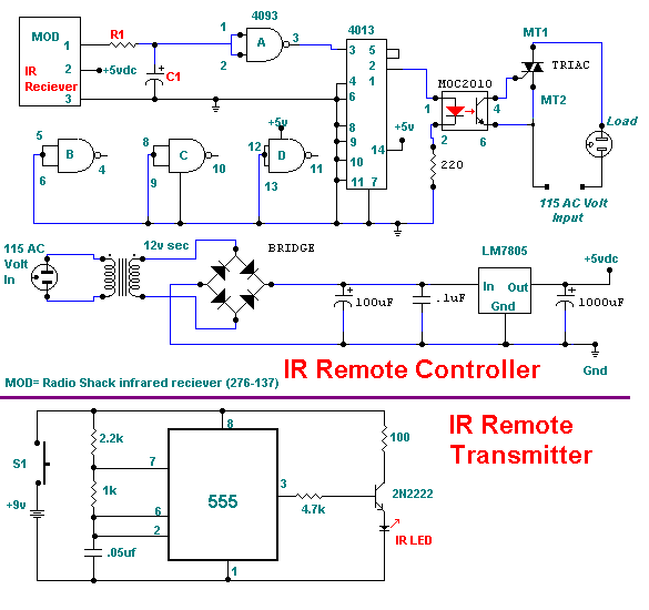
This circuit will allow you to turn on any piece of equipment that operates on 115 volts ac. The receiver circuit is based on the Radio Shack infrared receiver module (MOD), part number 276-137. It is also available from some of the other sources listed on my Links page. The MOD accepts a 40khz IR signal that is modulated at 4 khz.

Circuit Diagram

When a signal is received the MOD will go low. The sensitivity of the MOD is set by different values for R1 and C1. The values for R1 may need to be as high as 10,000 ohms and for C1 40uf. This will prevent the unit from turning on under normal lighting conditions. You will need to experiment with the values that work best for you. The output of the 4013 chip a flip flop toggles on and off with the reception of a IR pulse. The output of the 4013 turns on the MOC optical coupler which in turn switches on the triac and supplies power to the AC load.
read more...

IR Remote Control Extender (Mark 5)

The latest addition to my collection of Infra Red (IR) Repeater circuits. The Mark 5 is a much improved version of the Mark 1 circuit and has increased range and sensitivity. It is also immune to the effects ofambient light, daylight and other forms of interference. In addition it works with IR modulation freuencies in the range 30 to 120kHz making the Mk5 circuit the best choice for compatibility with remote controls.


Parts List:
R1,R2: 5M6 RESISTOR (2)
R3,R5: 3k3 RESISTOR (2)
R4: 120k RESISTOR (1)
R6: 220R RESISTOR (1)
R7: 47k RESISTOR (1)
R8: 120R RESISTOR (1)
R9: 10k RESISTOR (1)
R10: 2K2 RESISTOR (1)
R11: 100R RESISTOR 1 W (1)
C1,C3,C4: 22n polyester CAP (3)
C2: 100u electrolytic 25V(1)
C5: 100u electrolytic 25V(1)
Q1 BC107 (1) alternatives, BC107A, 2N2222, 2N2222A
Q2 BC109C (1) alternatives, BC109, BC549
D1: 1N4148 DIODE (1)
D2: Red LED (1)
IC1,IC2 CA3140E opamp (1)
IR1: SFH2030: (1)
IR2,3: TIL38 (2) or similar.

Design Philosophy:
This time I have returned to "first principles" and built a wideband infra red (IR) preamp which receives and re-transmits the entire baseband signal from a remote control handset.

It is designed to work with IR controls using 30-120KHz and should therefore work with just about any handset. In addition I have separated ambient (surrounding) light from the modulated light used by a remote handset. The major problem with the Mark 1 circuit is that it reacts to all light sources, ambient light producing a continous signal from the IR photo diode and is amplified by the rest of the circuit. I have published a modification to the original Mark 1 circuit, click here to view.

Noise Immunity:
It is difficult working with Infra Red, you cannot see it, and it is difficult to measure. A major barrier with this circuit was how to differentiate between daylight and an IR signal. Ambient light produces an almost continuous signal, changing little over several hours. A signal from an IR handset contains control pulses modulated with a carrier frequency (typically 36kHz) transmitted using an Infra Red photo diode. My solution used here, is a simple RC filter formed by C1 and R3.

At low frequency i.e. 50Hz the impedance of C1 is high, around 144k. The voltage gain of inverting op-amp IC2 is approximately R4 / R3, but at low frequency C1 is in series with R3 so the gain is now 120k / (3.3k + 144k) or less than unity. Daylight or ambient light will change slowly over several hours, in frequency terms this signal would be millihertz or less and C1's impedance will be megaohms.

A signal from an IR handset will be modulated at around 36KHz. At this frequency the impedance of C1 is very low, around 200 ohms. This has little effect on the input impedance of the op-amp stage and voltage gain will now be R4 / R3 or about 34 times. The impedance of capacitor C4 also helps noise rejection as its impedance change will allow more signal to pass into Q1 base at high frequencies and much less signal at line frequencies.

Circuit Details:
Light photons are received at IR1, this is an IR photo diode type SFH2030. A SFH2030F, which contains a daylight filter,may also be used instead of the SFH2030. The photo diode is reverse biased and when light strikes it, the energy of the IR signal releases additional charge carriers within the diode, allowing more current to flow. This current is amplified and converted to a voltage by the first CA3140 opamp, IC1. IC1 is wired as a current to voltage convertor, see below.


In an ideal current to voltage convertor the output voltage would be the product Rf multiplied by the input current. The non-inverting input would be tied to ground. In the Mark 5 circuit the output voltage is iR1 or about 5.6 Volts/uA appearing at pin 6 of IC1. The current generated by the SFH2030 photo diode when receiving a signal from a handset several metres away is less than 50 nA and requires the extreme high input impedance to avoid shunting the signal. There are two reasons for using the CA3140, the first is its high input impedance, over 1000G. The second reason is that normally the non-inverting input would be at 0V when working from split + and - supplies. In this single supply version the non-inverting input is returned to negative supply via R2. This can only be done with a Mosfet input, hence the choice for using the CA3140.

IC1 converta all current from the photo diode IR1 into a voltage. Although the SFH2030 is most sensitive at infra red wavelengths, it will produce tiny currents from daylight and also the 50/60Hz noise fields from flourescent and mains lighting. To minimize this, C1 and R3 form a high pass filter, allowing a 30kHz and higher signals to pass but blocking low frequencies. The impedance of C1 increases with decreasing frequency being 31k at 50Hz. Daylight for example, produces a contstant luminence, changing slowly over several hours, to which the impedance of C1 is effectively infinite.

The signal voltage from IC1 is now further amplified by IC2, gain being the ratio R4/R3 or 31dB. All opamps have a limit called the gain bandwidth product. The gain will fall to unity at the highest usuable frequency and be a maximum value at dc. Between these limits the gain falls with increasing frequency as shown in the bode plot for the CA3140 below:


Looking at the chart above, at 100kHz the maximum gain can only be about 30dB. However this is ample and boosts the received range of signals from a remote handset to the photo diode which have worked well up to 4 metres apart. Because R5 is returned to the negative supply a Mosfet input opamp must again be used. The output is again filtered by a high pass filter comprising C4 and the associated input impedance of Q1. R6, C2 and C3 provide decoupling for the IR preamplifier, C3 is in parallel with C2 because an electrolytic is not always a low impedance at high frequencies.

The IR output stage is comprised of Q1 and Q2 and associated components. The output is arranged so that with no input signal, Q1 is on and Q2 off; the visible LED, D2 will also be off. With no signal the 47k resistor biases the driver transistor, Q1 into full conduction. Its collector voltage will be near zero volts and the output transistor Q2, which is direct coupled to Q1 collector will therefore be fully off. Power drain will be minimal.

When an IR signal is receieved from a handset, the complete modulated signal will be amplified and fed via C4 into Q1 base. This is sufficiently strong enough to overcome the positive bias supplied by R7 and switch off Q1. This will happen many times a second, at the same frequency as the IR modulating signal sent by the handset. As Q1 switches off, its collector voltage rises to near full supply switching on Q1 and lighting the LED D2. Pulses of infra red at the same modulating frequency are then transmitted by the photo emitting diodes, IR2 and IR3. Because the signal is cleaner, (i.e. no daylight or 50/60Hz lamp fields included) then the series resistor R11 has been incresed in value to 100 ohms. The range from photo emitter diode to the equipment to be controlled has proved successfull at over 4 metres when powered from a 12 Volt supply. D1 helps to improve the turn off speed of Q1, thereby ensuring that the output waveform will be "squarer". It can be omitted but the circuit will perform better if D1 is included. A simulated transfer characteristic is shown below:

AC Transfer Charcteristic


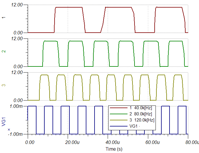
The ouput is measured between Q2 emitter and ground. A simulated transient response is shown below. Three graphs are produced with excitations of 40,80 and 120kHz.


Please note that the above waveforms are simulated using a perfect square wave input, with rise and fall times of zero seconds. The output is measured between Q2 emitter and ground with a 200 ohm resistive load. In the real world, the cable to the remote photo emitter LED's will contain both capacitance and inductance. This will increase both rise and fall times of the output signal. As with the Mark 1 circuit I recommend using speaker wire or bell wire to be used to cable the remote photo emitters.

My Prototype

Note that the veroboard layout below only includes the componets from the left of the schematic to C4, I had Q1 and Q2 on breadboard during this testing phase.


Setup and Testing:
There is little to adjust in this circuit. First I suggest disconnecting the wiring to the emitters IR2 and IR3. Switch on and D2 should be off. Aim a remote in the direction of IR1 and press any button D2 should light and be seen to flash when a button is held on the handset and go off when unpressed. If all is well reconnect the wiring to emitters IR2 and IR3. Without lenses, the light is quite directional and so you will need to aim it carefully at the remote equipment you are controlling. A digital camera, or camcorder can "see" into the Infra red range. This is useful to prove that IR2 and IR3 are producing output.

Veroboard Layout:
Below is a picture of my veroboard layout for the Mk 5 IR extender using Ron J's excellent veroboard images. Special thanks to Derek Smith for checking the veroboard layout and pointing out one small error (which is corrected now).


Special Note:I have omitted Diode D1 in my prototype and also the veroboard layout above, and the two images below. Click the links below to view the actual veroboard layouts. The veroboard drawing above shows the component site, the yellow circles represent the breaks on the bottom (track side).

Component side (106k)
Track side (97k)Note that this is reversed from component side.
For more help on vero layouts see this Practical Page.

Fault Finding:
If your circuit does not work, first check that your circuit is receiving power. Next compare the voltages to my prototype below. These checks are all made with a digital multimeter with a supply voltage of 12V DC. All checks are made with respect to ground (i.e. the back or negative meter probe is always connected to the negative or 0V power rail).

With no input signal:

IC1   Pin6       1.15V
IC2   Pin6       0V
Q1    base       0.8V
Q1    collector  0.13V
Q2    emitter    0V


With a strong input signal (handset same room less than 2meters away):

IC1   Pin6       1.15V
IC2   Pin6       0.15V
Q1    base       0.65V
Q1    collector  3.16V
Q2    emitter    2.79V


A good tip from Derek Smith (UK, who had problems with poor noise immunity in this circuit. Derek cured his fault by replacing the SFH2030 photo diode, the new SFH2030 provided much better noise immunity. So, if your voltage levels are similar to my prototype above then try replacing IR1.

If you still have problems with noise immunity check the supply voltage. Special thanks to Roch who found out that his 12V power supply was actually running at 16V. After reducing the voltage to 9V the problems disappeared for him. My original circuit ran happily from a 12V regulated supply.

Compatible Handsets:
If you build the mark 5 circuit please let me know the make and model of your remote control. I will add it to the list of compatible handsets below:-

Aiwa RC-ZVR01
Echostar URC-39756
Kameleon One for all remote (URC-8060) Maplins 6 way Audio/Video Switcher Hub order code L63AB
One for all remote
Panasonic EUR511200
Panasonic DVD player model no N2OAHC000012
Philips RC6512
Pioneer AXD7323
Pioneer VXX2801
Pioneer DVD remote
RCA systemlink 8 A-V
Saisho VR3300X
Sanyo vhs remote
Sony RM1- V141A VTR/TV
Sony RM-533
Sony RM-831
Std Sky digi box handset
Technics EUR64713
Xbox Remote
read more...

Wireless IR Headphone Receiver

A photodiode Dl feeds high gain IR remote control preamp 1C, a CA3237E. U2 is a PLL FM detector tuned to around 100 kHz. The detector output is amplified by U3 and it can drive a speaker or a set of headphones.

Wireless IR Headphone Receiver Circuit Schematic


read more...

TV Remote Control Jammer

This circuit confuses the infra-red receiver in a TV. It produces a constant signal that interferes with the signal from a remote control and prevents the TV detecting a channel-change or any other command. This allows you to watch your own program without anyone changing the channel !!    The circuit is adjusted to produce a 38kHz signal. The IR diode is called an Infra-red transmitting Diode or IR emitter diode to distinguish it from a receiving diode, called an IR receiver or IR receiving diode. (A Photo diode is a receiving diode).

TV Remote Control Jammer Circuit diagram:


There are so many IR emitters that we cannot put a generic number on the circuit to represent the type of diode. Some types include: CY85G, LD271, CQY37N (45¢), INF3850, INF3880, INF3940 (30¢). The current through the IR LED is limited to 100mA by the inclusion of the two 1N4148 diodes, as these form a constant-current arrangement when combined with the transistor and 5R6 resistor.
read more...

IR Remote Control Extender (Mark 4)

An Infra Red wired Repeater circuit to control appliances from a remote location.


Parts List:
R1: 1k Resistor (1)
R2: 3.3k Resistor (1)
R3: 10k Resistor (1)
R4: 15k Resistor (1)
R5: 2k2 Resistor (1)
R6: 470R Resistor (1)
R7: 47R Resistor (1) 0.5 Watt
PR1: 4.7k Preset (1)
C1,C3: 47u Elect(2)
C2: 1n Polyester 5% or better (1)
C4: 100u Elect(1)
Z1: 5V1 Zener (1)
Q1: BC549C or BC109C or 2N2222 (1)
Q2: BC337 or BC549 or ZTX450 (1)
IC1 : TSOP1738
IC2: 555 or 7555 (1)
LED1 5mm RED (1)
LED2,3 IR diode TIL38 or similar (2)

Alternatives to IC1 :

Everlight IR receiver module ELIRM 8621
Harrison electronics IR1
Vishay TSOP 1838
Radio Shack 276-0137
Sony SBX 1620-12
Sharp GP1U271R

Notes:
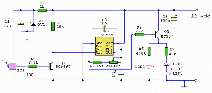
The signal emitted by an IR remote control contains two parts, the control pulses and a modulated carrier wave. The control pulses are used to modulate the carrier, a popular modulation frequency being 36 and 42KHz. The signal is radiated by an IR diode, typical wavelengths in the 850 and 950 nm region of the electromagnetic spectrum. Although this light is invisible to the human eye, it can be seen as a bright spot with a camcorder or digital camera.

In this circuit, the TSOP1738 IR module removes the carrier leaving only the slower control pulses ( 1 - 3KHz) which appear at the output. R1, C1 and Z1 form a smoothed 5 Volt supply for the IR module. Under quiescent conditions (no input signal) the output of the IR module is high. Transistor Q1 will be on, resulting in a low collector voltage, restting the 555 oscillator. Q1 also acts as a level shifter, converting the 5 Volt output signal to 12 Volts for the 555 timer. When an IR signal is received, decoded control pulses turn Q1 off and on. Each time Q1 turns off, pin 4 of the 555 timer goes high and an oscillation will be produced for the duration of each data pulse.

The 555 is wired as an equal mark/space ratio oscillator, the timing resistor R4, being connected back to the output of the timer, pin 3. The timing capacitor C2 is the other component in the timing chain. The pulse duration at pin 3 is defined as:-
 
T = 1.4 R4 C2

As the timing is crucialthe capacitor should have a tolerance of 5% or better and the power supply should be regulated. To allow for tolerance in components a 4k7 preset resistor is wired in series with R4. This adjustment allows R4 to be 15k to 19.7K creating output pulses of 21us and 27.58 us. As frequency is the reciprocal of periodic time then the oscillator adjustment is from 36.2Khz to 47KHz, allowing fine tuning for almost any appliance.

The final output stage uses a BC337 transistor in emitter follower. The output pulse will not be inverted, and the current through the IR photo emitters is around 30 mA dc. This is of course an average value, measured with a digital multimeter. The red led as always, is a visible indication that an input signal has been received. The circuit may be modified to use a fixed resistor in the timing chain as shown below. In this example a voltage regulator is also recommended to prevent changes in supply voltage altering the output pulse.


Setup and Testing:
Remove LED 2 and 3 and apply power. With no input signal LED 1 should be off. Press a button on a remote control in the same room as the circuit. LED 1 should flicker. If all is well, connect LED's 2 and 3 and point them in the direction of the appliance (TV or VCR etc). The cable to the LED's can exceed 100 metres if necessary, ordinary loudspeaker cable or bell wire is suitable. Set preset PR1 midway initially, it should work for all equipment. Most equipment is tolerant to within 5% so if you have for example a video that works at 42kHz and a TV that works at 38Kz tuning the modulation to 40KHz should allow both devices to operate. Any troublesome equipment, for example an Echostar receiver repeatedly press abutton on the handset while tuning PR1, you will find that it operates at some point. One IR LED may be used in place of LED2 & 3, but if there are two appliance in the same room, but in different locations, LED 2 can be aimed at a video, while LED3 aimed at a CD player for example. Below is how I discretely placed a photo emitter and plastered it directly into the wall:


Modifications:
An alternative output configuration is shown below. This uses a MOSFET to replace the original BC337 transistor. My thanks to Pete Griffiths for this modification and diagram.


Compatability:
If you make either the Mark 3 or 4 circuit please let me know if it works and the make and model of your remote control. I will add this to the database of compatible handsets below:-

Aiwa RC-ZVR01
Denon RC 554
Denon RC 921
Denon RC 924
Echostar T22605AA-00 * troublesome required careful tuning of PR1 to work
Kameleon One for all remote (URC-8060) Goodmans 97P1R2CPA1
Grundig SRC2
JVC LP20878-002
Matsui 28WN04
Mitsubishi 290P103A10
Mitsubishi EUR647003
NAD HTR2 (multi remote)
One for All 9910
Panasonic EUR511200
Philips RC6512
Pioneer AXD7323
Pioneer DV444
Pioneer VXX2801
Radioshack 1995
Saisho VR3300X
Sony RM-533
Sony RM-887
Sony RMT-V240
Sony RM-S325
Sony RM-DX50
Sony RM-U215
Sony RM-839
Sony RM-SCEX1
Sony RM-S336
Sony RM-D43M
Sony VCR
Technics EUR64713
read more...

IR Remote Control Extender (Mark 3)

This Mark3 version of the Infra Red extender is a special version designed to control appliances that use high frequency modulated IR remote controls.


Notes:
IR appliances use pulses (control signals) sent over a modulated IR carrier wave. The carrier wave may be modulated at various frequencies, 36-38KHz being the most popular.Some Satellite receivers use even higher frequencies than this. The IR1 remote module receives an infra red signal and separates control pulses from the modulation. To re-transmit, a 555 timer is configured as an astable oscillator. The 555 timer is controlled by the signal on the reset pin, high generating a carrier and low no carrier. Each control pulse turns on the oscillator for the duration of a logic high signal and off for a logic 0 signal, thereby creating a newly modulated IR signal. The IR module, part number IR1 is available from Harrison Electronics in the UK, IR1 may not be listed in their catalogue but if you ask for an IR1, they will send you the correct part. The IR1 arrives in a small aluminium case, the connections viewed from underneath are shown below:

Infra Red Module, IR1 Pinout

Harrison Electronics have limited supplies of the IR1 but as a replcement a standard IR module like the TSOP1838 may be used. The pinout is shown below:


The carrier frequency is determined by R1 and C3, values shown work at 39.7 kHz, but these may be altered to provide different carrier frequencies. The final CMOS 4049 invertor ensures that under "no signal" conditions both LED's are also off.

Parts List:

C1 100u 10V
C2 100n polyester
C3 120p silver mica
C4 100n polyester
R1 150k
R2 2k2k
R3 1k
R4 47R 1W
Q1 BC109C
IC1 LM7805
IC2 555
IC3 IR1 module from Harrison Electronics or TSOP1838
IC4 4049 CMOS Invertor LED1 Red LED (or any visible colour)
LED2 TIL38 or part YH70M from Maplin Electronics


PCB Layout (courtesy of Claudio from Italy):
First the component side of the board is shown below.


And now thw pcb itself.

The Mark 3 circuit is an improvement over the Mark 1 and 2 circuits, however the drive from Q1 inverts the polarity of the output pulse. In some cases this can cause problems so the output stage is rewired as an emitter follower. This is the basis for the Mark 4 circuit. If you still have problems then I would recommend trying the Mark 4 circuit.

read more...

A Basic IR Link

Description:
A basic Imfra Red Link for audio communication for distances upto 3 metres.


Notes:
Ovo je shema jednostavne bez?i?ne komunikacije sa malo komponenata .Diode d1 i d2 su infracrvene le-diode ,a foto transistor je tako?er infracrveni radi ?to manjeg vanjskog utjecaja .Domet ure?aja je oko 3m no on se mo?e promijeniti brojem le-dioda i naponom koji se dovede na diode.Na izlaz se ?ak mogu i direktno spojiti slu?alice.Link mo?e poslu?iti i za prijenos drugih vrsta signala..Na popisu komponenata nema kriti?nih dijelova i izrada sklopa je jako jeftina. Uz malo pa?nje ne moe da ne radi.
P.S Transistors can be replaced with 2N3904 and 2N2222

Notes:
In his circuit Milan has created a basic Infra Red transmitter and receiver. The transmitter comprises a single amplifying stage driving two series connected IR LEDS. The input source is connected to J1. Please note that the device will pass a small DC current through it and also directly bias the transistor. A suitable device is therefore a high output crystal microphone. These can produce high output voltages up to 1 Volt but this will be reduced by the transistors low input impedance.

The receiver is three stages, the first stage being a phototransistor. Stages two and three form a high gain darlington emitter follower, the bias for the whole stage derived through R2 and the phototransistor itself. C1 and R3 form a filter to reduce interference from flourescent lighting and other hum sources. The output is via Jack J2. Note also that the output device will pass a small DC current so a medium impedance loudspeaker or hwadphones are a good choice here.
read more...

IR illuminator for Night-Vision Tv Cameras and Scopes

This source uses LEDs and an astable oscillator to control the switch, duty-cycle, and effective IR illumination output.

 Circuit Diagram

read more...

IR Remote Control Extender (Mark 2)

This is an improved IR remote control extender circuit. It has high noise immunity, is resistant to ambient and reflected light and has an increased range from remote control to the extender circuit of about 7 meters. It should work with any domestic apparatus that use 36-38kHz for the IR carrier frequency. Please note that this is NOT compatible with some satellite receivers that use 115KHz as a carrier frequency.


Notes:
The main difference between this version and the previous circuit, is that this design uses a commercially available Infra Red module. This module, part number IR1 is available from Harrison Electronics in the UK. The IR module contains a built in photo diode, amplifier circuit and buffer and decoder. It is centerd on the common 38kHz carrier frequency that most IR controls use. The module removes most of the carrier allowing decoded pulses to pass to the appliance. Domestic TV's and VCR's use extra filtering is used to completely remove the carrier. The IR1 is packaged in a small aluminium case, the connections viewed from underneath are shown below:

Infra Red Module, IR1 Pinout

How It works:
The IR1 module (IC3) operates on 5 Volt dc. This is provided by the 7805 voltage regulator, IC1. Under quiescent (no IR signal) conditions the voltage on the output pin is high, around 5 volts dc. This needs to be inverted and buffered to drive the IR photo emitter LED, LED2. The buffering is provided by one gate (pins 2 & 3) of a hex invertor the CMOS 4049, IC2. The IR1 module can directly drive TTL logic,but a pull-up resistor, R4 is required to interface to CMOS IC's. This resistor ensures that the signal from a remote control will alternate between 0 and 5 volts. As TTL logic levels are slightly different from CMOS, the 3.3k resistor R4 is wired to the +5 volt supply line ensuring that the logic high signal will be 5 volts and not the TTL levels 3.3 volts. The resistor does not affect performance of the IR module, but DOES ensure that the module will correctly drive the CMOS buffer without instability.

The output from the 4049 pin 2 directly drives transistor Q1, the 10k resistor R1 limiting base current. LED1 is a RED LED, it will flicker to indicate when a signal from a remote control is received. Note that in this circuit, the carrier is still present, but at a reduced level, as well as the decoded IR signal. The CMOS 4049 and BC109C transistor will amplify both carrier and signal driving LED2 at a peak current of about 120 mA when a signal is received. If you try to measure this with a digital meter, it will read much less, probably around 30mA as the meter will measure the average DC value, not the peak current. Any equipment designed to work between 36 and 40kHz should work, any controls with carrier frequencies outside this limit will have reduced range, but should work. The exception here is that some satellite receivers have IR controls that use a higher modulated carrier of around 115KHz. At present, these DO NOT work with my circuit, however I am working on a Mark 3 version to re-introduce the carrier.

Parts List:
C1 100u 10V
C2 100n polyester
R1 10k
R2 1k
R3 33R 1W
R4 3k3
Q1 BC109C
IC1 LM7805
IC2 CMOS 4049B
IC3 IR1 module from Harrison Electronics See Last paragraph
LED1 Red LED (or any visible colour)
LED2 TIL38 or part YH70M from Maplin Electronics
Testing:

This circuit should not present too many problems. If it does not work, arm yourself with a multimeter and perform these checks. Check the power supply for 12 Volt dc. Check the regulator output for 5 volt dc. Check the input of the IR module and also Pin 1 of the 4049 IC for 5 volts dc. With no remote control the output at pin 2 should be zero volts. Using a remote control pin 2 will read 5 volts and the Red LED will flicker. Measuring current in series with the 12 volt supply should read about 11mA quiescent, and about 40/50mA with an IR signal. If you still have problems measure the voltage between base and emitter of Q1. With no signal this should be zero volts, and rise to 0.6-0.7 volts dc with an IR signal. Any other problems, please email me, but please do the above tests first.

PCB Template:
Once again a PCB template has been kindly drafted for this project by Domenico.


A magnified view showing the component side is shown below:


Alternatives to IC3:
The part number IR1 from Harrison Electronics is no longer available. They do supply an alternative IR decoder which I have tested and works. Other alternative Infrared decoders are shown below, note however that all DO NOT share the same pinout. I advise anyone making this to check the corresponding data sheets.
Vishay TSOP 1738
Vishay TSOP 1838
Radio Shack 276-0137
Sony SBX 1620-12
Sharp GP1U271R

Equipment Controlled Successfully:
If you have built this circuit and it works successfullt please let me know and I will build the list. Email details of the Manufacturer, device and remote control model number. The remote model number is usually on the front or back of the remote.
Technics CDP770   Remote: EUR64713
read more...

Headphone Amplifier with IR Communication

This low cost project can be used to reproduce an audio from TV without creating any disturbance from other people. No wire will be used by the circuit between the TV and the headphone because instead of using wires, it utilizes the invisible infrared light for the transmission of audio signals from the TV going to the headphone. The range that can be covered can reach up to 6 meters without using any lens but if required, the range can be made to extend with the use of lenses and reflectors with transmitters and receivers that comprise the IR sensors.

Headphone Amplifier with IR Communication Circuit diagram


Two series connected IR LEDS are being driven by the two-stage transmitter amplifier that uses the IR transmitter. The audio output from TV to the IR transmitter is coupled by using an audio output transformer that is reversely connected. The audio signals are amplified by the transistors BC547 & BD140. These audio signals are received from TV through the low output impedance windings for TV connection of the audio transformer while high impedance for IR transmitter connection.

A 9V source can power the IR transmitter with the LED functioning as power-on indicator.
read more...

IR Remote Control Extender Mark 1

Description
This circuit is used to relay signals from an Infra Red remote control in one room to an IR controlled appliance in another room.

Forward
I have seen these devices advertised in magazines, they sell for around £40-£50 and use radio to transmit between receiver and transmitter. This version costs under £5 to make and uses a cable connection between receiver and transmitter. For example, if you have a bedroom TV set that is wired to the video or satellite in another room, then you can change channels on the remote satellite receiver using this circuit. The idea is that you take your remote control with you, aim at the IR remote control extender which is in the same room, and this will relay the IR signal and control the remote appliance for you. The circuit is displayed below:


Parts List:

1 SFH2030 Photodiode
1 TIL38 IR emitting diode
1 5mm Red LED
2 4.7M 1/4W resistors
1 1k 1/4W resistor
1 2.2k 1/4W resistor
1 27ohm 1/2W resistor
1 BC337 transistor
1 CA3140 MOSFET opamp
The CA31340 is available in the US from Electronix Express, part number N103140.

Circuit Advantages
The advantage of this design against similar designs is that there are no adjustments to make or set-up procedures. However care should be taken to avoid ambient light reaching the photodiode. A dayligt filter type (black in colour) is recommended. Bellwire or speaker cable may be used to remotely site the IR emitting diode, since this design uses low output impedance and will not pick up noise. Some systems require coaxial cable which is expensive and bulky. The wireless variety of remote control extenders need two power supplies, here one is used and being radio are inevitably EM noise pollution. A visual indication of the unit receiving an Infra Red signal is provided by LED1. This is an ordinary coloured LED, I used orange but any colour will do. You will see LED1 flash at a rate of 4 - 40Hz when a remote control button is pressed. LED0 is an Infra Red Emitter Diode, this is remotely wired in the room with the appliance to be controlled. I used the type SFH487 which has a peak wavelength of 880nm. This is available in the UK from Maplin Electronics, order code CY88V. Most IR remote controls operate at slightly different wavelengths, between the range of 850 - 950nm. If you cannot obtain the SFH487 then any IR emitter diode that has an output in the above range should work.

About IR Remote Controls
As previously stated IR remote controls use wavelengths between 850 - 950nm. At this short wavelength, the light is invisible to the human eye, but a domestic camcorder can actually view this portion of the electromagnetic spectrum. Viewed with a camcorder, an IR LED appears to change brightness. All remote controls use an encoded series of pulses, of which there are thousands of combinations. The light output intensity varies with each remote control, remotes working at 4.5V dc generally will provide a stronger light output than a 3V dc control. Also, as the photodiode in this project has a peak light response at 850nm, it will receive a stronger signal from controls operating  closer  to this wavelength. The photodiode will actually respond to IR wavelengths from 400nm to 1100nm, so all remote controls should be compatible.

Circuit Description
The receiver is built around a silicon photodiode, the SFH2030 available from Maplin, order code CY90X. This photodiode is very sensitive and will respond to a wide spectral range of IR frequencies. There is a small amount of infra red in direct sunlight, so make sure that the diode does not pick up direct sunlight. If this happens, LED1 will be constantly lit. There is a version of the SFH2030 that has a daylight filter built in, the SFH2030F order code CY91Y. A TIL100 will also give good results here. A photodiode produces minute pulses of current when exposed to infra red radiation. This current (around 1uA with the SFH2030 and a typical IR control used at a distance of 1 meter) is amplified by the CA3140 opamp. The opamp is configured as a current to voltage convertor, producing an output of about 4.7 volts per uA of input current. The photodiode, can be placed up to a meter or so away from the circuit. Screened cable is not necessary, as common mode signals (noise) will be rejected. It is essential to use a MOSFET input type here as there is zero output offset and negligible input offset current. A 741 or LF351 can not be used in this circuit. The output from the opamp is amplified by the BC337 operating in common emitter mode. As a MOSFET opamp IC is used, its quiescent voltage output is zero and this transistor and both LED's will not be lit. The 1k resistor makes sure that the BC337 will fully saturate and at the same time limits base current to a safe level. Operating an IR remote control and pointing at the photodiode (SFH2030) will cause both LED's to illuminate, you will only see the visable coloured LED (LED1) which will flicker. Remote controls use a system of pulse code modulation, so it is essential that the signal is not distorted by any significant amount. Direct coupling, and a high speed switching transistor avoid this problem.

Construction
No special PCB is required, I built my prototype on a small piece of Veroboard. The pinout for the CA3140 is shown below. Note that only the pins labeled in the schematic are used, pins 1, 5 and 8 are not used and left unconnected.


Alignment
There is nothing to set-up or adjust in this circuit. The only thing to watch is that the emitting diode is pointing at the controlled device (video, CD player, etc). I found that the beam was quite directional. Also make sure that there is a direct line of sight involved. It will not work if a 5 foot spider plant gets in the way, for example. I had a usable range at 5 meters, but possibly more distance may be possible. As a check, place a dc volt meter across the 27 ohm resistor. It should read 0 volts, but around 2 or 3 volts when a remote control is aimed at the photodiode.

Specifications of Prototype
Having made my prototype, I ran a few tests :-

Current consumption  2mA standby    60mA operating  ( with 12V supply)
                                     2mA standby     85mA operating  (with 15V supply)
IR receiver range        < 1 meter
IR transmitter range    > 5 meters


It is difficult to measure the IR transmitter range as this is dependent upon a number of factors. The type of infra red control used and its proximity to the receiving photodiode, the voltage supply, the wavelength and efficiency of the IR emitter and the sensitivity of the controlled appliance all affect overall performance.

In Use
The reception range of the IR remote control to the photodiode depends on the strength of the remote control, but I had a working range of a meter or so, this needs bearing in mind when placing the circuit. Its also a good idea to wire LED1, the coloured LED near to the photodiode, that way, you know that the unit has received a signal. The IR emitter has a larger range, I had no problems at 5 meters but may possibly work further distances. The emitting diodes are quite directional, so make sure it is aimed directly at the appliance to be controlled. The IR emitting diode is small and can be placed out of sight. I drilled a small hole above the door frame. The emitter diode leads were insulated and pushed through this hole, leaving an inch or so to adjust the angle and position of the LED. From a distance, the clear plastic lens of the diode could not be seen.

Final Comments and Fault Finding
To date this has proved to be one of the most popular circuits on my site. Of all the email I receive about this circuit, most problems relate to the Infra Red photo diode. You must make sure that this is pointed away from sunlight, or use a type with daylight filter, otherwise LED1 will be constantly lit, and LED0 will be in operation also. This will draw excessive current and in some case overheat the BC337. The main problem is when using a different photo diode to the SFH2030. Any other photo diode LED should work, but you need to know its operating wavelength range beforehand. This will generally be described in the manufacturers data sheet or possibly described if you order from an electronic component catalogue. With these last two points in mind, you should be rewarded with a useful and working circuit.

PCB Template
This has been very kindly drafted by Domenico from Italy. First the copper side:


A magnified view from the component side is shown below. Unfortunately the transistor outline was reversed in the original diagram, my thanks go to Federico Laura for correcting this diagram :


Mark 1A Version
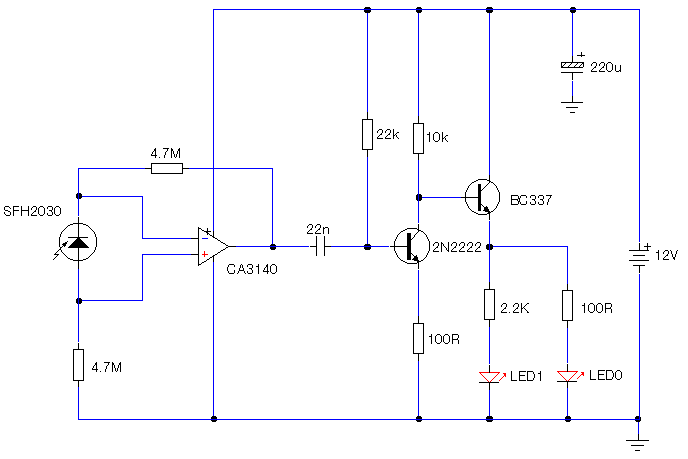
The modification to the Mark 1 circuit below separtes IR handset signals from daylight and mains powered lighting. The 22n capacitor has a high impedance at 50/60Hz and daylight but allows a modulated signal to pass. The 2N2222 transistor is biased on under no signal, the BC337 will be fully off. A control signal will switch off and on the 2N2222 transistor at the modulation frequency of the control, which in turn controls the BC337. As this is a cleaner signal, the series resistor may be increased to 100ohms.


read more...
 
Copyright © 2019 W3circuits.blogspot.com • All Rights Reserved.
back to top