Showing posts with label Indicator. Show all posts

Maximum Minimum Voltage Indicator

This circuit indicates which of three voltages in the range from about about -4V to about +4V - at A, B and C - is the highest by lighting one of three indicator LEDs. Alternatively, it can be wired to indicate the lowest of three voltages or to indicate both the highest and lowest voltages. Op amps IC1a, IC1b & IC1c are wired as comparators, while the three indicator LEDs and their series 1kO current limiting resistors are strung across the op amp outputs to implement the appropriate logic functions.

Maximum Minimum Voltage Indicator Circuit Diagram:

Indicator Circuit Diagram

For example, LED A will light only when pin 8 of IC1c is low (ie, A greater B) and pin 7 of IC1b is high (ie, A greater C). Similarly, LED B will light only when pin 8 of IC1c is high (ie, B greater A) and pin 1 of IC1a is low (ie, B greater C). LED C works in similar fashion if the voltage at C is the highest. Note that if all the LEDs and their parallel 1N4148 diodes are reversed, the circuit will indicate the lowest of the three input voltages. And if each 1N4148 diode is replaced by a LED, the circuit will indicate both the highest and lowest inputs.
read more...

Flat Battery Indicator

This small circuit was developed to monitor the battery in a model hovercraft. The lift in the model is produced by an electric motor driving a fan. To avoid the possibility of discharging the rechargeable battery pack too deeply, the design lights a conspicuous LED mounted on the model when a preset threshold voltage is reached. The circuit only uses a few components, which helps keep the total weight of the model down. The circuit connects to the model only across the two points where the voltage to be monitored can be measured. These also supply power to the circuit.

The best place to connect the circuit is not at the battery terminals, but rather at the motor connections. The circuit is suitable for use with nominal battery voltages of 4.8 V to 9.6 V (four to eight 1.2 V cells). For example, if there are six cells in the battery, its nominal terminal voltage will be 7.2 V. A discharge threshold voltage of around 1 V per cell is appropriate, which means that for six cells the threshold is 6 V. We now need to set the voltage UZ across the adjustable Zener diode D1 (an LM431) to about 0.5 V less than the threshold voltage at which we want LED D2 to light.

Flat Battery Indicator Circuit Diagram: 

Indicator Circuit Diagram


This voltage is controlled by the choice of the value of resistor R1. As indicated in the circuit diagram, this is done with the help of a trimmer potentiometer (R1.A) with a fixed resistor (R1.B) in series. Using the suggested values (10 kΩ for both the potentiometer and the fixed resistor) allows the discharge threshold voltage to be set between about 5.5 V and 8 V. For lower or higher voltages R1.B should be made correspondingly smaller or larger. Once the desired value of UZ has been set the total resistance (R1.A plus R1.B) can be measured and a single fixed-value resistor of this value substituted at R1.

In the example mentioned of a six-cell battery, a voltage of 7.2 V will appear at the emitter of T1 when the battery is charged. At its base is UZ, which should be 5.5 V (6 V – 0.5 V) in the case of a discharge threshold voltage of 6 V. As long as the battery voltage remains at least 0.5 V higher than UZ, T1 will conduct and T2 will block, with the result that LED D2 will not light. If the battery voltage should fall below about 6 V (UZ + 0.5 V), T1 will block, T2 will conduct and LED D2 will light. To ensure stable operation of the circuit R6 provides a small amount of switching hysteresis. By adjusting the resistor value between 100 kΩ and 220 kΩ the amount of hysteresis can be varied.

The current drawn by the circuit itself is less than 5 mA (as measured with a battery voltage of 7.2 V). When the LED lights an additional 10 mA (the LED current) is drawn, for a total of around 15 mA. The adjustable Zener diode can be replaced by a fixed Zener with a voltage 0.5 V less than the desired threshold. Resistors R1 and R2 can then be dispensed with. A flashing LED can be used for D2 (without series resistor R7). An acoustic alarm can be provided by replacing D2 and R7 by a DC buzzer with a suitable operating voltage.

read more...

Motor Bike and Car Turning Signal Indicator with 555 Timer IC

Here is electronic circuit project for Motor Bike and Car Turning Signal Indicator. In our daily life we see vehicles turning indicators when they turn left or right. It looks like Simple LED Blinking. But it's not only simple blinking LEDs inside indicators of vehicles. Here we are building a fancy Car/Bike Turning Indicator Circuit using 555 Timer IC, with four LEDs glowing one by one in a particular pattern and we can control the speed or frequency of this LED indicator by simply turning a Potentiometer.

Motor Bike and Car Turning Signal Indicator Circuit Diagram:

Indicator

Parts List:

  • BC547 or MPS A42 NPN transistor -4
  • Bread Board -1
  • 555 Timer IC -1
  • 1K -1
  • 10k POT -1
  • 10K -6
  • 68K -1
  • Power Supply
  • LED -4
  • 10uF Capacitor -1
  • 470uF -1
  • 1N4148 Diode -2
  • 9V Battery -1
  • Jumper wire
In this Bike Turning Signal Indicator circuit, we have used one 10K and 1K resistors and a capacitor for generating a delay. The 1n4148 diode is connected in reverse bias at the output pin of 555 timer IC to maintain a constant current. Due to base current BC547/MPS42A (NPN) Transistor drive, the LED’s ON and OFF. LEDs are connected to the transistor through a 220ohm resistor with respect to Vcc. This 220ohm resistor will save LED to may get damaged.


read more...

36V Battery Level Indicator

This battery level indicator offers (5) LEDs that light up progressively as the battery voltage increases. This is a update of the 24V Battery Level Indicator. While designed for 36V systems, it is easily modified to 24V, 48V or 60V simply by changing two resistors.

  • Red:              Power Connected (0%) (essentially always on)
  • Orange:        Greater than 35V (25%)
  • Yellow:        Greater than 37V (50%)
  • Green:         Greater than 39V (75%)
  • Blue:           Greater than 41V (100%) (full charge is about 41 to 42V)

Of course, you may select your own colors if desired.

36V Battery Level Indicator Circuit Diagram:


Indicator Circuit Diagram

High voltage issues

One limiting factor is the LM339 that has an absolute maximum voltage rating of 36V –and it is not good practice to operate near that point. The solution involves running the IC power rail off a zener shunt regulator. Shunt regulators are very simple, inexpensive and robust –good for this application. However, the LM339 open collector outputs cannot drive LEDs powered from the battery bus due to the same maximum voltage limitation. There are two solutions for this: increase the current rating of the shunt regulator so that it can power the LEDs, or run the LEDs via a cascode amplifier arrangement –I chose the cascode amplifier.

Cascode amplifier

A cascode amplifier is a configuration where one transistor feeds a 2nd transistor that is connected in the common base configuration. This configuration is generally used for RF amplifiers. In this circuit it offers one great property –low voltage in, high voltage out. By tying the bases of these transistors to the 13V bus, the LM339 open collector drive transistors never see more than 13V. However, the cascode transistors may drive LEDs that are tied to a much higher voltage –up to 80V using the MPS-A16. By limiting the emitter current, the LED current is automatically limited to the same value. While this is relatively busy, it places virtually no burden on the shunt regulator.

Circuit Operation

D1 is the voltage reference zener. Tied to this is a string of divider resistors (R2-6) that set the various fixed voltage levels. R7 & 8 form a voltage divider to that divides the battery voltage by a factor of 9. The quad comparator compares the various voltages from the two dividers.

For calibration, connect to a voltage source that can be set to the highest LED threshold (41V in this case). Then adjust the calibration pot until D2 flickers. The remaining LEDs will switch on close to the indicated voltage –accuracy of those voltages may suffer slightly, but should be close.

The LEDs are biased to operate at 2.3mA which is reasonably bright for high efficiency LEDs. This current can be adjusted simply by varying the emitter driver resistors (R9 through R13). To reduce standby power, a push-to-test pushbutton may be used.

Bug

Testing on variable voltage turned up an interesting bug –when the voltage was turned down to about 10V, all LEDs lit again. This was traced to Zener D9 dropping out of conduction thus starving the voltage divider. Connecting a 33K resistor across D9 corrected this little problem without affecting anything else.

Picture of project:

36V Battery Level Indicator Circuit DiagramLevel Indicator Circuit Diagram36V Battery Level Indicator Circuit Diagram


 Author By: JIM KEITH

read more...

Water Level Indicator Using CMOS ICs

A very simple low cost water level indicator circuit can be designed using this schematic circuit . This water level indicator is based on a simple CMOS IC CD4066 and indicates the amount of water present in the overhead tank and also gives an alarm when the tank is full. As you can see in the circuit diagram the circuit uses the widely available CD4066, bilateral switch CMOS IC to indicate the water level through LEDs.

Water Level Indicator Using CMOS ICs Circuit Diagram:

Water Level Indicator Circuit Diagram

When the water is empty the wires in the tank are open circuited and the 180K resistors pulls the switch low hence opening the switch and LEDs are OFF. As the water starts filling up, first the wire in the tank connected to S1 and the + supply are shorted by water. This closes the switch S1 and turns the LED1 ON. As the water continues to fill the tank, the LEDs2 , 3 and 4 light up gradually.

The no. of levels of indication can be increased to 8 if 2 CD4066 ICs are used in a similar fashion.
When the water is full, the base of the transistor BC148 is pulled high by the water and this saturates the transistor, turning the buzzer ON. The SPST switch has to be opened to turn the buzzer OFF.

As you can see this electronic liquid sensor circuit require very few external components and need to be powered from a 6 volts DC power supply .
read more...

Indicator for Dynamic Limiter

The indicator described here is specifically designed for adjusting the dynamic limiter described elsewhere in this edition and checking whether the maximum level of the reference voltage (P1) needs to be modified. Her e we use a 4 -to -16 decoder IC (type 4514) to monitor the state of the four-bit up/down counter in the limiter circuit. This IC can be powered from the ±8 V supply voltages of the limiter. The limiter board has a 6-way connector (K5) that provides access to the four counter outputs and the sup-ply voltages. Connector K1 of the indicator circuit can be connected to K5 on the limiter board.

Indicator for Dynamic Limiter Schematic:

Indicator for Dynamic Limiter

One output of the 4514 goes high for each unique 4-bit combination on its inputs, while the other outputs remain logic Low. A separate current-limiting resistor is connected in series with each LED. It was not possible to use a common cathode resistor here because most LEDs have a maximum reverse blocking voltage of only 5 V, while the supply voltage here (16 V) is a good deal higher.

The 16 LEDs ar ranged in a r ow pr ov ide a ‘fluid’ indication of the control process. You can enhance the display by using different colours for the first and last LEDs, such as red for D1 (maximum gain) and green for D16 (minimum gain), with yellow for the rest of the LEDs. While observing signals from various sources (TV set, DVD, media player, etc.), you can easily use the 16 LEDS to monitor the behaviour of the limiter and adjust the setting of potentiometer P1 in the limiter circuit. It must be set such that D16 only lights up at the maximum signal level. If this is not possible and D16 remains lit a good deal of the time regardless of the position of P1, it will be necessar y to increase the value of P1. Of course, it is also poss-ible to adjust P1 so the strongest signal source extends slightly above the control range of the limiter.

This circuit can easily be assembled on a small piece of prototyping board. The current consumption is around 4 mA.

read more...

Check Inductors With This Simple Q Meter

While LCR meters are readily available at reasonable cost, they do not measure the Q of an inductor. This circuit enables you to measure the Q of inductors with the aid of an RF signal generator. A capacitor is connected in parallel with the inductor to form a tuned circuit. By varying the frequency, you can measure the resonance frequency of the tuned circuit and its -3dB bandwidth. The Q is then the resonance frequency divided by the -3dB bandwidth. Transistor Q1 is an emitter follower acting as input buffer to drive RF transformer T1. The secondary winding of T1 then drives the parallel tuned circuit formed by the inductor under test (Lx), T1’s secondary and tuning capacitor VC.

The tuned circuit so formed is buffered by JFET Q2 and transistor Q3 which form a cascode stage with about 3dB of gain. The JFET provides a high impedance so that the loading of the tuned circuit is minimal (note: an MPF102 can be substituted if you cannot obtain a 2N5485). The RF output from Q2's collector can be monitored by an oscilloscope to easily find the point of resonance and read the frequency. Alternatively, the RF output can be read by an external frequency meter. Diodes D1 & D2 and the 5.6nF capacitors form a voltage doubler rectifier to drive a 100µA DC meter so that the resonance can be found (in the absence of an oscilloscope).

Check inductors with this simple Q meter:

Check inductors with this simple Q meter

Trimpot VR1 provides a sensitivity adjustment for the meter. Transformer T1 is wound on a 12mm diameter ferrite toroid core. The primary winding consists of 50 turns of 0.2mm diameter enamelled copper wire, while the secondary is a single turn consisting of a strip of brass 0.5mm thick and 2.5mm wide bent into a horseshoe shape and threaded through the centre of the toroid. VC is a small AM tuning capacitor with both gangs connected in parallel.

To measure Q, the output of the RF signal generator should be around 0.5V peak. Adjust the frequency until the meter's reading peaks, then adjust VR1 so that the meter reads full scale (100µA). Read the resonance frequency F0 from the frequency scale of the signal generator or better still, the reading on a frequency meter.

Next, increase the signal frequency until the meter reads 70µA and note this frequency as F2. That done, reduce the frequency on the signal generator below the resonance frequency until the meter again reads 70µA and note this frequency as F1. The Q can now be calculated as:

Q = F0/(F2 - F1)

While using a variable tuning capacitor will enable a wider range of inductors to be tested, the main advantage is estimating the distributed capacitance of the inductor as well. To do this, you have to calibrate the tuning scale with a capacitance meter, by measuring the capacitance across the tuning capacitor with no inductor connected. This is done with the unit switched off. Marking off increments of 20pF should be sufficient.

Set the tuning capacitor to say ¼ of its maximum value and note this value as C1. Adjust the RF signal generator frequency so that the inductor under test is at resonance and note this frequency as F0. Now set the RF generator frequency to half F0, adjust the tuning capacitor until resonance and note this capacitance as C2. The distributed capacitance of the inductor is (C2 - 4C1)/3.

read more...

Power On Indicator

Power On Indicator Circuit diagram. Some types of electronic equipment do  not provide any indication that they are  actually on when they are switched on.  This situation can occur when the back-light of a display is switched off. In addition, the otherwise mandatory mains  power  indicator  is  not  required  with  equipment  that  consumes  less  than  10 watts. As a result, you can easily forget  to switch off such equipment. If you want  to know whether equipment is still drawing power from the mains, or if you want  to have an indication that the equipment  is switched on without having to modify the equipment, this circuit provides a solution.

One way to detect AC power current and  generate a reasonably constant voltage  independent of the load is to connect a  string of diodes wired in reverse parallel in series with one of the AC supply  leads. Here we selected diodes rated  at 6 A that can handle a non-repetitive  peak current of 200 A. The peak current  rating is important in connection with  switch-on  currents.  An  advantage  of  the selected diodes is that their voltage  drop increases at high currents (to 1.2 V  at 6 A).

This means that you can roughly  estimate the power consumption from  the brightness of the LED (at very low  power levels). The voltage across the diodes serves as  the supply voltage for the LED driver. To  increase the sensitivity of the circuit, a  cascade circuit (voltage doubler) consisting of C1, D7, D8 and C2 is used to double  the voltage from D1–D6. Another benefit  of this arrangement is that both halve- waves of the AC current are used. We use  Schottky diodes in the cascade circuit to  minimise the voltage losses.

Circuit diagram

The LED driver is designed to operate the LED  in blinking mode. This increases the amount  of current that can flow though the LED when  it is on, so the brightness is adequate even  with small loads. We chose a duty cycle of pproximately 5 seconds off and 0.5 second  on. If we assume a current of 2 mA for good  brightness with a low-current LED and we can  tolerate a 1-V drop in the supply voltage, the  smoothing capacitor (C2) must have a value of  1000 µF. We use an astable multivibrator built around two transistors to implement a  high-efficiency LED flasher.

It is dimensioned to minimise the drive current of  the transistors. The average current consumption is approximately 0.5 mA with a  supply voltage of 3 V (2.7 mA when the  LED is on; 0.2 mA when it is off). C4 and  R4 determine the on time of the LED (0.5  to 0.6 s, depending on the supply volt-age). The LED off time is determined by  C3 and R3 and is slightly less than 5 seconds. The theoretical value is R × C × ln2,  but the actual value differs slightly due to  the low supply voltage and the selected  component values.

Power On Indicator Circuit diagram:

Indicator Circuit diagram
Diodes D1-D6 do not have to be special  high-voltage diodes; the reverse volt-age is only a couple of volts here due  the reverse-parallel arrangement. This  voltage drop is negligible compared to  the value of the mains voltage. The only  thing you have to pay attention to is the  maximum load. Diodes with a higher  current rating must be used above 1 kW.  In addition, the diodes may require cool-ing at such high power levels.  Measurements on D1–D6 indicate that  the voltage drop across each diode is  approximately 0.4 V at a current of 1 mA.  Our aim was to have the circuit give a  reasonable indication at current levels  of 1 mA and higher, and we succeeded  nicely. However, it is essential to use a  good low-current LED.


Caution: the entire circuit is at AC power potential. Never work on the circuit with the mains cable plugged in. The  best enclosure for the circuit is a small,  translucent box with the same colour as  the LED. Use reliable strain reliefs for the  mains cables entering and leaving the  box (connected to a junction box, for  example). The LED insulation does not  meet the requirements of any defined insulation class, so it must be fitted such that it  cannot be touched, which means it cannot  protrude from the enclosure.

read more...

Fuse Monitor Indicator

This electronic circuit project of fuse monitor indicator, its a very simple way to check if a fuse has blown without removing it from its holder.

Fuse Monitor Indicator Circuit Diagram:

Fuse Monitor Indicator Circuit Diagram


The idea for this project may have come to me in a flash of inspiration
read more...

Low-Cost Low State Car Battery Indicator

Here is very simple low-cost electronic circuit project of low state car battery indicator circuit. This electronic circuit diagram designed using few common electronic parts. This low state battery electronic project can be used to monitor car battery voltage.

Low-Cost Low State Car Battery Indicator Circuit Diagram:

Indicator Circuit Diagram

The warning light LED indicates when battery indicates battery voltage falls bellow level set by 10k potentiometer, if the battery is defective or needs charging if cranking drops battery voltage bellow preset safe limit.

This circuit project is very simple so it not requires some other explanation.


read more...

Game Show Indicator Lights (Who's First)

The circuit below turns on a light corresponding to the first of several buttons pressed in a "Who's First" game. Three stages are shown but the circuit can be extended to include any number of buttons and lamps.

Game Show Indicator Lights Circuit Diagram:

Indicator Lights Circuit Diagram

Three SCRs (silicon controlled rectifiers) are connected with a common cathode resistor (50 ohm) so that when any SCR conducts, the voltage on the cathodes will rise about 7 volts above the voltage at the junction of the 51K and 1K ohm resistors and prevent triggering of a second SCR. When all lamps are off, and a button is pressed, the corresponding SCR is triggered due to the voltage at the divider junction being higher than the cathode. Once triggered, the SCR will remain conducting until current is interrupted by the reset switch. Or, you can just turn the power off and back on.

A 50 ohm, 5 watt resistor was selected to produce a 10 volt drop at 200 mA when a single 25 watt lamp comes on. Higher wattage lamps would require a lower value resistor, and visa versa. For example to use 60 watt lamps and maintain the 10 volt drop, the peak current would be 60/160 = 375 mA and the resistance would be E/I = 10/.375 or about 27 ohms at 3.75 watts. The SCRs are "Sensitive Gate' types which trigger on about 200 uA and the gate current is around 1.5 mA when the first button is pressed. The 1N914 diodes in series with the buttons gates are used to prevent a reverse voltage on the gate when a button is pressed after an SCR is conducting. The two 51 ohm resistors will be fairly large in physical size (compared to a 1/4 watt size) and should be rated for 5 watts of power or more. Use caution and do not touch any components while the circuit is connected to the AC line.

Adding a Buzzer:

The relay shown in parallel with the 50 ohm cathode resistor can be used to momentarily power a buzzer with an external circuit through the contacts. The 1000 uF capacitor causes the relay to energize for about one second, longer times can be obtained with a larger capacitor.

Parts List:

Quantity       Description                   Radio Shack Part Number

1         4 Amp/400 Volt Bridge Rectifier            276-1173
3         Silicon Controlled Rectifier (SCR)         NTE5457
3         120 VAC/ 25 Watt incandescent lamp
1         50-100 microfarad/ 200 volt capacitor
1         1000 microfarad / 35 volt capacitor        272-1032
1         50 ohm resistor/ 5 or 10 Watt              271-133
3         Push Button Switch (normally open)
1         Push Button Switch (normally closed)
3         2K resistor, 1/4 watt                      271-1325
4         1N914 Diode
1         51K resistor, 1 watt
1         2 Amp Fuse                                 270-1064
1         Relay (SPDT) 9 Volt DC, 500 ohm coil       275-005


read more...

Blown Fuse Indicator

This blown fuse indicator will work with a wide range of DC supply voltages from 5V to 50V. It illuminates LED1 when the fuse blows. With the fuse intact, Q1 is held off and there is no bias current available for the base of Q2. So the LED is off. When the fuse blows, a small current flows via the base-emitter junctions of Darlington transistor Q1, through its base resistor R1 and then via the load. Typically this current will be around 20μA and this turns on Q1 which provides base current to Q2 which then turns on to illuminate the LED.

Blown Fuse Indicator Circuit Diagram:

Indicator Circuit Diagram

The emitter current of Q2 is limited by Q3 which turns when the current reaches about 10mA, to shunt base current away from Q2. The three resistor values not given in the circuit are dependent on the supply voltage and can be calculated from the following simple equations:
  • R1(kΩ) = V(DC)/0.02 = 560kΩ for 12V DC
  • R2(kΩ) = V(DC)/2 = 5.6kΩ for 12V DC
  • R3(Ω) = V(DC)/0.02 = 560Ω for 12V DC
R3 should be included for voltages above about 20V otherwise the heat dissipation in Q2 will be too great. At lower voltages it can be omitted. Any general purpose NPN transistors can be used for Q2 and Q3, provided they will handle the DC supply voltage. The PNP Darlington, Q1, could be an MPSA65, available from Dick Smith Electronics (Cat Z-2088).

Author: Keith Gooley - Copyright: Silicon Chip


read more...

Brake Failure Indicator

Here is a brake failure indicator circuit that constantly monitors the condition of the brake and gives an audio-visual indication. When the brake is applied, the green LED blinks and the piezobuzzer beeps for around one second if the brake system is intact. If the brake fails, the red LED glows and the buzzer stops beeping. The circuit will work only in vehicles with negative grounding. It also gives an indication of brake switch failure. In hydraulic brake systems of vehicles, a brake switch is mounted on the brake cylinder to operate the rear brake lamps.

Brake Failure Indicator Circuit Diagram:

Indicator Circuit Diagram

The brake switch is fluidoperated and doesn’t function if the fluid pressure drops due to leakage. The fluid leakage cannot be detected easily unless there is a severe pressure drop in the brake pedal. This circuit senses the chance of a brake failure by monitoring the brake switch and reminds you of the condition of the brake every time the brake is applied. The circuit uses an op-amp IC CA3140 (IC2) as voltage comparator and timer NE555 (IC3) in monostable configuration for alarm. Voltage comparator IC2 senses the voltage level across the brake switch. Its non-inverting input (pin 3) gets half the supply voltage through potential divider resistors R3 and R4 of 10 kilo-ohms each.

The inverting input (pin 2) of IC2 is connected to the brake switch through diode D1, IC 7812 (IC1) and resistor R2. It receives a higher voltage when the brake is applied. Normally, when the brake is not
applied, the output of IC2 remains high and the red LED (LED1) glows. The output of IC2 is fed to trigger pin 2 of the monostable through coupling capacitor C2. Resistor R1 is used for the input stability of IC2.

IC1 and C1 provide a ripple-free regulated supply to the inverting input of IC2. IC3 is wired as a monostable to give pulse output of one second. Timing elements R7 and C4 make the output high for one second to activate the buzzer and LED2. Usually, the trigger pin of IC3 is high due to R6 and the buzzer and LED2 remain ‘off.’ When the brake pedal is pressed, pin 2 of IC2 gets a higher voltage from the brake switch and its output goes low to switch off the red LED. The low output of IC2 gives a short negative pulse to the m o n o s t a b l e through C2 to trigger it.

This activates the buzzer and LED2 to indicate that the brake system is working. When there is pressure drop in the brake system due to  leakage, LED1 remains ‘on’ and the buzzer does not sound when the brake is applied. The circuit can be assembled on any general-purpose PCB or perforated board. Connect point A to that terminal of the brake switch which goes to the brake lamps. The circuit can be powered from the vehicle’s battery.

The circuit requires well-regulated power supply to avoid unwanted triggering while the battery is charging from the dynamo. IC4, C6 and C7 provide regulated 12V to the circuit. The power supply should be taken from the ignition switch and the circuit ground should be clamped to the vehicle’s body. A bicolour LED can be used in place of LED1 and LED2 if desired. 


read more...

Light Level Indicator Using a Window Comparator

The second example below uses a LDR (light dependent resistor) to indicatesome desired light level. The LDR has a large dynimic range and varies inresistance from less than 100 ohms on a cloudy day to over a megohm in totaldarkness. A 2K pot was used to adjust the window range for usual room lightconditions. This setup might also be used to indicate sunrise/sunset conditions.

Light Level Indicator Circuit Diagram

Light Level Indicator Circuit Diagram

The proto board picture below shows the circuit wired to measure lightlevel using a LDR and 2K potentiometer. The green (window) LED is litindicating the light level is about right to take the picture.


Indicator Circuit Diagram

read more...

Temperature Range Indicator Using a Window Comparator

A window comparator usually employs 2 comparators with one output indicatingthe input is somewhere between two limits. In these examples, a thirdcomparator is added to display all three conditions where the input is inthe center range, or higher, or lower.

The first example uses a thermistor to indicate the temperature is near68 degrees within about +/- 5 degree tollerance. The thermistor measures33K at around 68 degrees and varies about 3570 ohms over a range of 10 degrees.Using a 12 volt supply, the thermistor voltage will be 6 volts in the centerof the range. As the temperature increases 10 degrees, the total resistancefalls 3750 ohms, the current will be 12/ (66K -3750) =193uA and the thermistorvoltage will be 193u * (33k -3750) = 5.65 volts.

Temperature Range Indicator Circuit Diagram

Indicator Circuit Diagram

This represents a voltage change of (6 - 5.65) = 350 millivolts for a 10 degree change. The center resistorof the window voltage divider must then drop 350 millivolts. Using 20K resistorson the top and bottom of the window voltage divider produces a current of(6 - (.350/2)) / 20K = 291uA, and the center resistor is .350/291u = 1.2K

When the temperature is in the center of the window range, the voltage atpins 5 and 6 will be 1/2 the supply voltage, or 6 volts in this case.The voltage divider (20K, 1.2K, 20K) produces a voltage of around 5.8 atpin 4 and 6.2 at pin 7. Since the voltage at pin 5 (6 volts) is more positivethan the voltage at pin 4 (5.8 volts), the output at pin 2 will be a highlevel. At the same time, the voltage at pin 7 (+ input) is higher thanpin 6 (- input) causing pin 1 to also be a high level.

This condition produces a high (12 volt) level at pin 10 (- input) which produces a lowlevel at pin 13, lighting the window LED indicating the temperature is inthe window range. As the thermistor voltage moves above the upper 6.2 limit,pin 1 will switch low, extinguishing the window LED and illuminating the(Low Temp) LED. Similar action happens as the thermistor voltage moves belowthe lower 5.8 limit causing pin 2 to switch low (Over Temp LED) while theother two LEDs remain off.


read more...

Flashing LED Battery Status Indicator

A Battery-status Indicator circuit can be useful, mainly to monitor portable Test-gear instruments and similar devices. LED D1 flashes to attire the user's attention, signaling that the circuit is running, so it will not be left on by mistake. The circuit generates about two LED flashes per second, but the mean current drawing will be about 200µA. Transistors Q1 and Q2 are wired as an uncommon complementary astable multivibrator: both are off 99% of the time, saturating only when the LED illuminates, thus contributing to keep very low current consumption.

Flashing LED Battery Status Indicator Circuit Diagram

Indicator Circuit Diagram


The circuit will work with battery supply voltages in the 5 - 12V range and the LED flashing can be stopped at the desired battery voltage (comprised in the 4.8 - 9V value) by adjusting Trimmer R4. This range can be modified by changing R3 and/or R4 value slightly.

When the battery voltage approaches the exhausting value, the LED flashing frequency will fall suddenly to alert the user. Obviously, when the battery voltage has fallen below this value, the LED will remain permanently off.

To keep stable the exhausting voltage value, diode D1 was added to compensate Q1 Base-Emitter junction changes in temperature. The use of a Schottky-barrier device (e.g. BAT46, 1N5819 and the like) for D1 is mandatory: the circuit will not work if a common silicon diode like the 1N4148 is used in its place.

Note:

Mean current drawing of the circuit can be reduced further on by raising R1, R7 and R9 values.
read more...

Power Resumption Alarm and Low-Voltage Protector

The circuit described here protects your electrical appliances like AC motors from damage due to low voltage at power-on. It remains standby without giving power to the load after power resumes. The load can be switched on only manually. This prevents damage to the device if it is 'on' when power resumes.

unregulated power supply is derived from a 12V-0-12V, 300mA step-down transformer and rectifying diodes D2 and D3. The rectified DC is made ripple-free using capacitor C3. An audio/video indicator (piezobuzzer and LED3) is provided along with the power supply for power resumption.

When power is switched on, capacitor C4 charges through the piezobuzzer and LED3, making both of them active. The piezobuzzer beeps and LED3 glows for a few seconds. When capacitor C4 is fully charged, the cathode of the LED becomes high inhibiting further flow of current through the buzzer.

When the power is off, capacitor C4 discharges through resistor R9.

The circuit uses IC CA3140 (IC1) as a voltage comparator to detect voltage changes in the unregulated power supply due to AC mains. Mains voltage changes in the primary as also the secondary winding of the transformer, which is sensed by IC1 to energise/de-energise the relay. Zener diode ZD1 provides a reference voltage of 3V to make transistor T1 conduct. Preset VR1 adjusts the breakdown point of ZD1.

Fig. 1: Power supply circuit with resume indicator

Eletronics Circuit Diagrams

When the voltage level is normal, zener diode ZD1 breaks down and transistor T1 is forward-biased. Capacitor C1 provides time delay of a few seconds to avoid any fluctuation affecting the device during power-on. When transistor T1 conducts, the inverting input (pin 2) of IC1 goes low. However, IC1 does not give a high output as its power supply depends on the conduction of SCR1 (BT169). So manual operation is necessary to energise the relay.

When push-to-on swish S1 is pressed, SCR1 fires to provide voltage to IC1 at its pin 7. As the voltage level at the non-inverting input (pin 3) of IC1 is half of the supply voltage, its output becomes high and the relay (RL1) energises. LED2 glows to indicate the high output of IC1 and activation of relay.

When the line voltage goes below 180V, the secondary voltage of the transformer also drops, say, below 12 volts, ZD1 cease to conduct and the collector of T1 becomes high. This high voltage at the inverting input (pin 2) of IC1 makes its output low. The relay de-energises to stop power to the device.

Fig. 2:  Low-voltage Protector Circuit Diagram

Eletronic Circuit Diagrams

Assemble the circuit on a general-purpose PCB and enclose in a suitable cabinet. Use a 12V PCB-mounted relay. Provide holes for LEDs and switch S1 on the front side of the case. Connect AC power voltage to the motor (load) through the common and normally-open (N/O) contacts of the relay. After assembly and checking the circuit, switch on the circuit and wait for a few minutes. LED1 will gradually become bright due to the charging of capacitor C1. Press S1 to energise the relay. Adjust VR1 so as to make LED1 fully on. This will allow easy latching of the relay.

read more...

ULN2004 Water Level Indicator

This ULN2004 electronic project circuit diagram design is a very simple water level indicator circuit project . This ULN2004 water level indicator circuit is very simple and require few external electronic parts .

ULN2004 is a high voltage, high current darlington arrays that contain seven open collector darlington pairs with common emitters . Each channel rated at 500mA and can withstand peak currents of 600mA.

 ULN2004 Water Level Indicator Circuit Diagram

As the water level rise in the tank , it comes in contact with probes P1 through P7 and thereby makes pins 7 trough 1 high sequentially . The corresponding output pins 10 trough 16 go low one after other and LED1 through LED7 will light up . When water comes in contact with the last probe P7 , the buzzer connected to the last pin 16 will sound .

This electronic circuit project must be powered from a fixed output DC voltage that will provide an output voltage between 9 and 12 volts .
read more...

Pressed Button Sound Indicator

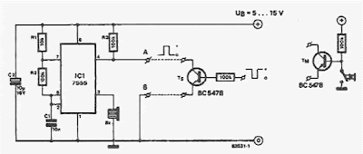
sing this electronic scheme can be made an electronic circuit that allows a sound indication for a button.The circuit is based on a 7555 integrated timer (CMOS version of the well-known ment 555) is connected as a multivibrator astabil .His output is a rectangular pulse with a frequency of 700 Hz, which is used to control a small buzzer.


Pressed Button Sound Indicator Schematic 


Pressed button sound indicator circuit 
 
The circuit will oscillate be prevented if pin 4 of integrated circuit is connected to 0 V.
 
read more...

Off-Hook Telephone Line Indicator

The circuit is designed to connect in parallel with the telephone line, to monitor and detect if any telephone in the same line is busy, with the indication of the LED and which is self-powered so that it does not provide any load on a telephone line.

Light Emitting Diode (LED) – a semiconductor diode that is commonly a source of light when electric current pass through it Metal Oxide Semiconductor Field Effect Transistor (MOSFET) – a device utilized for switching and amplification of signals BS108 – a 250 mA and 200 Volts small signal MOSFET designed for high voltage, high speed switching applications such as relay drivers, CMOS logic, line drivers, TTL or microprocessor to high voltage interface and high voltage display drivers Diode Bridge – also known as bridge rectifier which has four diodes arranged in a bridge configuration where the output voltage has the same polarity with either polarity of the input voltage 1N4007 – a general purpose plastic rectifier with reverse voltage from 50 Volts to 1000 Volts and forward current of 1.0 Ampere

When none of the telephone lines is in use or on-hook, the voltage across the line is around 48V. In this state, the gate of transistor Q2 is shorted to its source during the conduction of Q1. This causes the LED to be disabled while Q2 is turned OFF. When one telephone extension along the telephone line changes to off-hook or in use condition, a voltage drop from 5V to 15V is detected. This will in turn cause Q1 to turn OFF because of the very low voltage across the gate of Q1 which is equal to 6% of the line voltage. Transistor Q2 then will be biased at around half of the line voltage.

Off-Hook Telephone Line Indicator Circuit Diagram


Off-Hook Telephone Line Indicator

 The sudden line drop of voltage triggers Q2 to light up the LED that will give a sign that the line is in use. Using the same line, the circuit is unseen with other telephone devices. A current-limiting resistor is used to maintain the low current of LED1 while the local telephone line parameters dictate the variation of other component’s values. The power of the circuit is provided by the telephone line. Other voltage protection may be used with some reliable design in addition to the current-limiting resistor. This is important to avoid any grounding effects from conducting surfaces within the circuit.

To ensure that transistor Q1 is fully biased while the line is free or not in use where LED1 is OFF, a 500K ohm MOSFET trimmer is used for the desired adjustment. A MOSFET is a three-terminal semiconductor component with a conducting channel in its output and a built-in capacitor at its input. To increase the values of any of the two resistors connected to the gate of Q2, a 200V MOSFET can be used in the place of Q2 if BS108 is not available. However, plain transistors like the bipolar junction can be used but with lower values to allow greater currents to pass through the line that is not in use. The bridge rectifier comprising of four 1N4007 diodes are performing the conversion of AC input into DC output.

MOSFET can function in two ways. The first is known as depletion mode wherein the channel shows its maximum conductance in the absence of a voltage on the gate. The second way that the MOSFET can function is known as enhancement mode wherein the device is not conducting even in the absence of a voltage on the gate because no channel is produced. A channel is being created with the application of a voltage to the gate. To generate better conductivity, greater voltage to the gate is required.

MOSFET drivers are applied in electronic motor control for different types of motors. Also, they are specifically used with long duty cycles, high operating frequency above 200 KHZ, lower output power, and wide load variations. The largest application of MOSFETs are the switched mode power supplies and in battery charging applications. In transducer drivers for high power devices such as light bulbs and motors, large current output with a small input is provided by MOSFETs. Since they are more non-linear than BJTs while producing less distortion, they can be utilized with Hi-Fi amplifiers. In constructing integrated circuits, MOSFETs are very useful since they can be made very compact. Although MOSFETs can get damaged by static electricity at higher voltages, they still provide several advantages as compared to other transistors which include faster switching time than BJT, lower losses than BJT, very small switching current, and least effects of temperature.

This telephone line indicator does not only tell when a telephone line is in use if a plurality of telephones are all setup to the same telephone line, but also prevents interruptions during personal calls. Additionally, it can also help to prevent costly and unwanted disruption of modem calls and fax, it alerts a person when a call is done and the phone is free to use, and the LED light indicates the line is in use.

To avoid any injury, it is a prerequisite to take extra precautionary measures when connecting any circuit to the telephone lines, which can produce life-threatening voltages during normal operation. During a lightning storm, it is better to keep distance from telephone lines.. Legal aspects are imposed in different countries for connecting things to telephone lines. The circuit should be better built with a plug-in cord for easy removal in case of fault occurrences. Otherwise, it would be best to consult a licensed telephone operator.
read more...
 
Copyright © 2019 W3circuits.blogspot.com • All Rights Reserved.
back to top