Showing posts with label Control. Show all posts

Rotative Speed Regulator Borer, Driller Controller

This rotative speed regulator circuit schematic allows to control the holing speed of your borer or driller machine. This project is based on the fact that if the load grows, the voltage decrease and current increase.

Driller Controller Circuit Diagram:


Controller Circuit Diagram
 
Use this circuit to control the speed of revolutions of your drilling mill or bench drill.
read more...

FAN 7710 Ballast Control

This electronic project Using the FAN 7710 Ballast Control IC for Compact Fluorescent Lamps developed using Fairchild’s unique highvoltage process and system-in-package (SiP) concept can be designed a very simple low cost fluorescent lamp driver electronic project .The FAN7710 ballast control controls internal high-voltage stress and delivers 20W to the lamp at 320VDC voltage.

FAN 7710 Ballast Control Circuit Diagram:


Control Circuit Diagram
 
FAN7710 ballast control incorporates a preheating /ignition function, controlled by an user-selected external capacitor, to increase lamp life. The FAN7710 detects switch operation from after ignition-mode through an internal active Zero-Voltage Switching (ZVS) control circuit.

Parts List:

Control Circuit Diagram
 
The AC line input voltage (230 VAC 50 Hz) is rectified to provide a bus voltage of approximately 320 volts DC. Startup resistor R1 supplies initial power to the FAN7710 IC.The IC begins to oscillate and the charge pump circuit consisting of C2, D2 and D7 supplies the current to the VDD pin, which gets regulated through the internal 15-V shunt regulator.
read more...

Mbed Microcontroller Prototyping

The mbed micro-controller 40 pin was developed for prototyping the mbed compiler lets you write programs in C + +, and then compile and download them to run on the micro-controller.

Mbed Microcontroller Prototyping

The mbed compiler is a Web App in the cloud, you do not have to install or configure anything to wear. Compatible with any operating system and any place, the software is online and ready to be used, you will only need a computer or netbook with an Internet connection.
read more...

Automatic fan controller

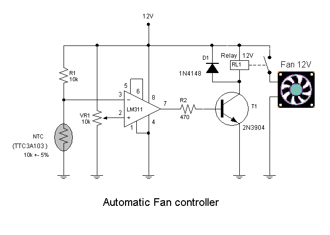
This circuit will turn on/off 12V DC fan or CPU fan when temperature above normal temperature.You can set turn on temperature by adjust VR1.

Automatic fan controller Circuit Diagram:
controller Circuit Diagram
This circuit use an NTC (Negative temperature coefficient)which is a thermistor is one in which the zero-power resistance decreases with an increase in temperature. So If temperature increate the voltage at pin 3 on LM311 will decreated .The resistance of NTC is about 10K at 25'c.

VR1 should be multi-turn potentiometer type such 10K/25 turn.
read more...

DC Motor Speed Controller using a LM317

A very simple DC motor speed controller circuit can be constructed using a LM317 voltage regulator integrated circuit. This DC motor speed controller can be used for speed control  of mini drills or for other small DC motors. This motor controller circuit will provide a large output current. The maximum output current from the secondary turns of the transformer shout provide 1.5 times of the maximum DC output current. The output voltage and the speed (rpm) is set by the P2 variable resistor.

DC Motor Speed Controller using a LM317: 

DC Motor Speed Controller using a LM317:

As soon as the current drawn exceeds a certain value, T2 will be switched on. This results in a base current for T3 so that R5 is in parallel with R6. This automatically raise the output voltage to counter a threatened drop in rpm.  The moment at which this action occurs is set by P1.

read more...

Outdoor Lighting Controller

When you step out of your brightly-lit house  into the darkness, it takes a while for your  vision to adjust. A solution to this problem  is this outdoor light with automatic switch-off. As a bonus, it will also make it a little bit  easier to find the keyhole when returning  late at night. Often no mains neutral connection is avail-able at the point where the switch-off timer  is to be installed, which makes many circuit  arrangements impractical.

However, the circuit here is designed to work in this situation. The design eschews bulky components such as transformers and the whole unit can  be built into a flush-mounted fitting. The circuit also features low quiescent current consumption.

Outdoor Lighting Controller Circuit Diagram:

Lighting Circuit Diagram

The circuit is star ted by closing switch (or  pushbutton) S1. The lamp then immediately receives power via the bridge rectifier. The drop across diodes D5 to D10 is 4.2 V, which provides the power supply for the delay circuit itself, built around the CD4060 binary  counter.

When the switch is opened the lighting sup-ply current continues to flow through Tri1. The NPN optocoupler in the triac drive circuit detects when the triac is active, with antiparallel LED D1 keeping the drive sym-metrical. The NPN phototransistor inside the  coupler creates a reset pulse via T1, driving  pin 12 of the counter. This means that the  full time period will run even if the circuit is retriggered. The CD4060 counts at the AC grid frequency.  Pin 3 goes high after 213clocks, which corresponds to about 2.5 minutes. If this is not long  enough, a further CD4060 counter can be cascaded. T2 then turns on and shorts the internal LED of opto-triac IC2; this causes Tri1 to  be deprived of its trigger current and the light  goes out. The circuit remains without power until next triggered.

The circuit is only suitable for use with resistive loads. With the components shown (in particular in the bridge rectifier and D5 to  D10) the maximum total power of the connected bulb(s) is 200 watts. As is well known, the filament of the bulb is most likely to fail at the moment power is applied. There is little risk to Tri1 at this point as it is bridged by  the switch. The most likely consequence of overload is that one of diodes D1 to D6 will  fail. In the prototype no fuse was used, as it would not in any case have been easy to change. However, that is not necessarily recommended practice!

Circuits at AC line potential should only be constructed by suitably experienced persons and all relevant safety precautions and  applicable regulations must be observed during construction and installation.

Author : Harald Schad - Copyright : Elektor
read more...

Computer Room Temperature Control Using TC620

Here is a very simple electronic circuit project for Computer room temperature control circuit using TC620 temperature sensor.

Computer Room Temperature Control Using TC620:

Computer

As shown in the figure, the circuit consists of the temperature sensor, control devices, the upper and lower temperature display, relay control motor circuit, waves analog voice circuit and AC buck rectifier circuit.
read more...

Temperature Controller Using Lm3911

It is very low-cost and simple electronic circuit project for temperature controller using the LM3911 highly accurate temperature measurement and control system designed in a single monolithic chip.

The output voltage of the LM3911 is directly proportional to temperature in degrees Kelvin at 10 mV/degree K. As you can see in this circuit diagram, LM3911 temperature sensor chip require few additional components.

Temperature Controller Circuit Diagram:

Controller Circuit Diagram
 
The resistor network consists of R1, R2, and R3 is used to provide the set point voltage reference for the feedback input of the LM3911. R4 resistor is used to limit the current through the internal voltage reference of the LM3911. R5 resistor pulls the output of the IC high when the temperature is bellow the set point. The internal resistor is in series with a diode that allows a switching voltage up to 35 volts to be used.
By modifying the R2 variable potentiometer you will modify the set point of the temperature controller.

This simple temperature controller circuit needs to be powered from a 12 volts DC power supply.

read more...

Simple Traffic Light Controller

Here the simple traffic light controller which is could be used to educate kids rudiments of traffic light guidelines. The circuit utilizes easily available electronic parts. It generally consists of rectifier diodes (1N4001), a 5V regulator 7805, two timers circuit using IC 555, two relays (5V, single-changeover), three 15W, 230V light bulbs and also several discrete parts.
Traffic Light Controller Circuit Diagram:

Controller Circuit Diagram

Mains electrical power is stepped down by transformer X1 to provide a secondary output voltage of 9V, 300 mA – AC. Then the transformer output current is rectified by a full-wave bridge rectifier composed of diodes D1 through D4, filtered by capacitor C1 and also regulated by IC 7805 (IC1).
IC2 is wired as a multivibrator with ‘on’ and ‘off’ periods of about 30 seconds each with the part values determined. Once mains power switch is turned on, pin 3 of IC2 goes high for 30 seconds. This, in turn, energises relay RL1 via transistor T1 and the red bulb (B1) glows through its normally-open (N/O) contact. At the same time, mains power is turned off from the pole of relay RL2. As the ‘on’ time of IC2 ends, a triggers IC3 through C5. IC3 is set up as a monostable with ‘on’ time of about 4 seconds, which indicates pin 3 of IC3 will stay high for this period of time and energise relay RL2 through driver transistor T2. The amber bulb (B2) thus lightings up for 4 seconds.
Immediately after 4-second time period of timer IC3 at pin 3 lapses, relay RL2 de-energises and also the green bulb (B3) lights up for the rest of ‘off’ period of IC2, which is about 26 seconds. The green bulb is turned on through the normally closed (N/C) contacts of relay RL2. So when mains electrical switch is turned on, red light will light up for 30 seconds, amber for 4 seconds and green for 26 seconds.
You can easily build this circuit on a general purpose PCB and enclose in a protected box. The box needs to have sufficient area for installing transformer X1 and also two relays. It could be installed near 230V AC, 50Hz power supply or mounted on the PVC tube applied in assembly of the traffic light box.
Design of the traffic light container box is demonstrated in following image:
 
Traffic Light Controller
 
A stout cardboard box of 30x15x10cm3 is needed for housing the lights. To make certain durability, work with a 10x45cm2 plywood plate having 1.5 centimeters thickness and also secure onto it three light outlets and the box utilizing nuts and bolts or screws. Make three tubes of thin aluminium sheet, which is easily offered in equipment stores. The inner diameter of aluminium tubes ought to be such that these can well match on the light outlets. Working with a sharp knife, make holes opposite the outlets carefully. Wire the outlets at the back and take the cables out through the PVC tube.
To begin with, fix three 15W light bulbs (B1 through B3) and then press on the tubes. Support the other ends of the tubes in the holes made on the front panel of cardboard box. Sandwich gelatine papers of the three colors in between two sheets of cardboard and fix over the tubes. The visibility of red, amber and also green lights enhances with their installation on the tubular shape.
 
Source link:-Cirucits-Projects
 
read more...

How to Build a Automatic Lighting Controller

How to build a automatic lighting controller circuit. The governor following is intended to regulate the light intensity incandescent 220 V. The components in a relatively few, which means it can easily be mounted onto a small plate. After the build, we recommend you place it inside the box which is flush mounted switch ON / OFF the lamp. Setting the switch to ON, the lamp will light after about 400 msec, a delay is probably negligible.

Automatic Lighting Controller Circuit Diagram:

Automatic Lighting Controller

But when the state enters the ON OFF, then mesolathei a period of 20 sec, the brightness of the lamp remains unchanged to start falling out soon after.  The last feature is particularly useful when we want to have a little time from the moment you 'close' switch. Once the switch S1 set to ON, the capacitor C2 begins to charge through R1, C1 and bridge D1-D4. The Zener diode D5 limits the voltage across the capacitor to about 15 n. After awhile, the diode D6 LED illuminates, causing the appearance of a significant drop in voltage across R3.

The change in voltage results in stimulation of Triac TR1, which in turn lit the lamp is connected to K2. We note that the resistor R3 is a type of LDR, the price that depends on the intensity of light falling on it. When the switch is moved to OFF, the capacitor C2 will discharge through R 1, R2 and D6. During discharge, the LED D6 reduces the brightness continuously, which causes a gradual decrease in voltage across R3. The increasing resistance of R3 is causing in turn change the firing angle of the Triac, which eventually results in a smooth decrease in brightness of the lamp.

The time required for complete extinction of the lamp is defined by the regulatory P1 and directly dependent on the time constant R2-C2. The circuit works properly only if it falls on the R3 only light diode O6 rather diffuse room light. The type of LDA is not critical. Choose a length with a 5mm.


read more...

How to Build Compressor Protector

How to build compressor Protector circuit. This circuit monitors the power-line (ac) voltage. When a power failure occurs, on restoration of power, the circuit a dds a five-minute delay before energizing Kl, which protects the compressor against limited low voltage.

Compressor Protector Circuit Diagram:

Compressor Protector

 Ul is a 16-stage counter with an integral oscillator that is set to divide by 8192. R7, R8, and C4 set the oscillator frequency to about 25 Hz, which produces a total count interval of 300 seconds (5 minutes). After this time, pin 8 Ul goes high, which forward biases Ql, triggers SCR1, and activates Kl. Up to 30 A can be switched.

read more...

How to Build AC Line Current Detector

This circuit will detect AC line currents of about 250 mA or more without making any electrical connections to the line. Current is detected by passing one of the AC lines through an inductive pickup (L1) made with a 1 inch diameter U-bolt wound with 800 turns of #30 - #35 magnet wire. The pickup could be made from other iron type rings or transformer cores that allows enough space to pass one of the AC lines through the center. 

Only one of the current carrying lines, either the line or the neutral should be put through the center of the pickup to avoid the fields cancelling. I tested the circuit using a 2 wire extension cord which I had separated the twin wires a small distance with an exacto knife to allow the U-bolt to encircle only one wire.

AC Line Current Detector Circuit Diagram

Detector Circuit Diagram

The magnetic pickup (U-bolt) produces about 4 millivolts peak for a AC line current of 250 mA, or AC load of around 30 watts. The signal from the pickup is raised about 200 times at the output of the op-amp pin 1 which is then peak detected by the capacitor and diode connected to pin 1. The second op-amp is used as a comparator which detects a voltage rise greater than the diode drop. The minimum signal needed to cause the comparator stage output to switch positive is around 800 mV peak which corresponds to about a 30 watt load on the AC line.

The output 1458 op-amp will only swing within a couple volts of ground so a voltage divider (1K/470) is used to reduce the no-signal voltage to about 0.7 volts. An additional diode is added in series with the transistor base to ensure it turns off when the op-amp voltage is 2 volts. You may get a little bit of relay chatter if the AC load is close to the switching point so a larger load of 50 watts or more is recommended. The sensitivity could be increased by adding more turns to the pickup.

read more...

Stepper Motor Controller Using by A3952S

Using the A3952S stepper motor controller ( designed by Allegro MicroSystems ) we can design a very simple and useful motor driver circuit that can be used in many electronic applications . A3952S stepper motor controller is capable of continuous output currents up to 2 A and operating voltages range up to 50 V. Internal fixed off-time PWM current-control circuitry can be used to regulate the maximum load current to a desired value. The MODE terminal can be used to optimize the performance of the device in microstepping / sinusoidal stepper motor drive applications.

A3952S Stepper Motor Controller Circuit diagram


When the average load current is increasing, slow-decay mode is used to limit the switching losses in the device and iron losses in the motor. The thermal performance in applications with high load currents and/or high duty cycles can be improved by adding external diodes in parallel with the internal diodes. In internal PWM slow-decay applications, only the two top-side (flyback) diodes need be added. For internal fast-decay PWM, or external PHASE or ENABLE input PWM applications, all four external diodes should be added for maximum junction temperature reduction .

As you can see in the schematic diagram , this stepper motor driver circuit require two A3952S circuits and other few additional electronic components.
read more...

Headphone Amplifier with IR Communication

This low cost project can be used to reproduce an audio from TV without creating any disturbance from other people. No wire will be used by the circuit between the TV and the headphone because instead of using wires, it utilizes the invisible infrared light for the transmission of audio signals from the TV going to the headphone. The range that can be covered can reach up to 6 meters without using any lens but if required, the range can be made to extend with the use of lenses and reflectors with transmitters and receivers that comprise the IR sensors.

Headphone Amplifier with IR Communication Circuit diagram


Two series connected IR LEDS are being driven by the two-stage transmitter amplifier that uses the IR transmitter. The audio output from TV to the IR transmitter is coupled by using an audio output transformer that is reversely connected. The audio signals are amplified by the transistors BC547 & BD140. These audio signals are received from TV through the low output impedance windings for TV connection of the audio transformer while high impedance for IR transmitter connection.

A 9V source can power the IR transmitter with the LED functioning as power-on indicator.
read more...

Mini Drill Speed Regulator Using Voltage Regulator

With an integrated voltage regulator connected reverse to a mini drill can be adjusted speed within certain limits so that it remain constant, independently of load. In the scheme presented below the electronic speed control is made by a voltage regulator, allowing use of motor which require a supply voltage from 2.5 V to 12 V at a maximum current absorbed by an 1A. Output voltage is determined by the ratio of resistances R1 and R2. Uout = (R1 + R2) Uc/R2. Uc is equal to -2.23 V for 79GU voltage regulator.

Mini Drill Speed Regulator Circuit diagram


Integrated controller is designed to keep constant the value of -2.23 V, the voltage from common terminal .
With the P2 potentiometer can be adjusted the degree of coupling (coupling the output voltage increases with increasing output current). Thus remains constant preset speed. Maximum voltage measured when the P2 is turned up must be about 20% lower than the maximum allowable voltage of the motor (if is not, the value of R1 should be reduced or enlarged accordingly). Voltage regulator is designed with thermal protection, but it must be mounted on a properly dimensioned radiator.
read more...

Stepper Motor Controller Using the NJM3771

An very simple stepper motor driver circuit can be designed using the NJM3771 stepper motor driver integrated circuit designed by New Japan Radio Co. Ltd. This stepper motor driver electronic project is very simple to design and require few external components . 

Stepper Motor Controller Circuit diagram


The NJM3771 IC is especially developed for use in microstepping applications in conjunction with the matching dual DAC (Digital-to-Analog Converter) NJU39610. The NJM3771 contains a clock oscillator, which is common for both driver channels; a set of comparators and flip-flops implementing the switching control; and two H-bridges with internal recirculation diodes. Also this stepper motor driver project supports a wide range input voltage : +5 V is required for logic and +10 to +45 V for the motor powering . The maximum output current that is supported by this circuit is around 650 mA per channel. The NJM3771 stepper motor driver has an selectable slow fast current decay for improved high speed Microstepping .

The output current to the motor winding is mainly determined by the voltage at the reference input and the value of the sensing resistor, RS. The voltage across the sensing resistor is fed back to the comparator via a low-pass filter section, to prevent erroneous switching due to switching transients ( the recommended filter component values, 1 kohm and 820 pF). This driver IC is designed for bipolar motors, i.e., motors that have only one winding per phase but unipolar motor, having windings with a center tap, can also be used .
read more...

2500W Phase Control

This circuit controls resistive and inductive loads up to 2,500W. It's main functional device is an integrated phase control circuit - Siemens TLE3103. It contains its own power supply, a zero voltage crossing detector circuit and a logic driver. An additional feature is the low voltage input to enable/disable triac firing enabling/disabling the logic driver. The function is as follows: pin13 TLE3103 open (floating), trigger output active, tied to ground trigger output disabled.

2500W Phase Control  Circuit diagram


An UP and a DOWN button control a 32-step digital potentiometer (IC2, AD5228) via the debouncer IC1 (MAX6817). The potentiometer has a power on reset pin which might be tied to ground causing the potentiometer to start at midscale, or to VCC causing it to start at zero scale. The desired function is selectable using jumper JP1. The triac (capable of driving 40A loads) is a bit overkill for the desired power but the BTA41 has an isolated body and therefore handling of the board under voltage is less dangerous as it is with phase on the package. The circuit uses a 68μH inductance, but this might be replaced with a 100 resistor, then replacing the inductance C5 should have a value of 47nF.
read more...
 
Copyright © 2019 W3circuits.blogspot.com • All Rights Reserved.
back to top