Portable systems often include circuitry that derives power from an
external source, such as USB. When the system disconnects from the USB
supply, a battery takes over and supplies current via a dc/dc converter.
A diode-OR connection (Figure 1 offers the easiest way to ensure that
the supply voltage doesn't sag during this switchover to the battery.
The diode's forward voltage drop, however, can reduce battery life and
efficiency.
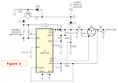
The single-cell, boost-converter circuit with external PFET (Figure 2) is an improvement over the diode-OR connection. The PFET, Q1, coupled with IC1's internal gain block, forms a linear regulator. The USB power supply has a diode-OR connection to Q1's source. Setting the boost converter's output to 3.4V allows the drain of Q1 to regulate to 3.3V. This configuration produces negligible loss in Q1. The bus-supply voltage available to USB devices ranges from 4.4 to 5.25V.
When you connect the bus, it forward-biases D1 and causes the boost converter to idle. The converter continues to idle as long as its output remains above the 3.4V regulation point. The bus supply serves the load and activates the current source to charge the battery.
Adjusting R1 allows you to set the current-source output to charge the nickel-metal-hydride cells at a level one-tenth the battery's capacity. Disconnecting the circuit from the USB supply causes the boost converter to cease idling and supply current to the load via the battery. Figure 3 shows that the load current suffers no interruption during a switchover from USB to battery.
A boost-converter circuit is an improvement over the simple diode-OR connection.
The single-cell, boost-converter circuit with external PFET (Figure 2) is an improvement over the diode-OR connection. The PFET, Q1, coupled with IC1's internal gain block, forms a linear regulator. The USB power supply has a diode-OR connection to Q1's source. Setting the boost converter's output to 3.4V allows the drain of Q1 to regulate to 3.3V. This configuration produces negligible loss in Q1. The bus-supply voltage available to USB devices ranges from 4.4 to 5.25V.
When you connect the bus, it forward-biases D1 and causes the boost converter to idle. The converter continues to idle as long as its output remains above the 3.4V regulation point. The bus supply serves the load and activates the current source to charge the battery.
These waveforms (bottom trace, load voltage) show that the load current suffers no interruption during a switchover from USB to battery.


0 comments:
Post a Comment